MAN00000772_SI-G200BB_SVCPDFA.pdf - 第684页
Chan ge Proc edure for R T Axis Timin g Be l t Change Pro cedure fo r RT A x is Ti m ing Belt [Necess a r y Jigs] He ad block Te nsion Mete r (UNIT T A U-507) Be lt Tensio n JIG [Disassembly] 1 Fo r the re moval proce du…
Change Procedure for RN axis Timing Belt
[Reassembly]
10 Apply the new timing belt to pulley on the head
side in the reverse order of the above procedure.
11 Apply the RN timing belt to the pulley on the motor side.
1. Confirm the condition of item 2 again.
Temporarily attach the RN bracket.
12 Adjust the tension of RN timing belt, refer to RPGB-10501-1
.
13 Attach the inner shaft. (Removed it item8)
[Adjustment]
14 Adjust the nozzle detection sensor position.
Refer to HLGB-10413-01.
15 Calibration
1. HLGB-10207-01 RN ORG Offset Setting
2. HLGB-10414-01 Nozzle Phase Adjustment
3. HLGB-10304-01 Calibration
Change Procedure for RN-axis
Timing Belt
SHEET
3/3
RPGB-10801-1
Change Procedure for RT Axis Timing Belt
Change Procedure for RT Axis Timing Belt
[Necessary Jigs]
Head block
Tension Meter (UNITTA U-507)
Belt Tension JIG
[Disassembly]
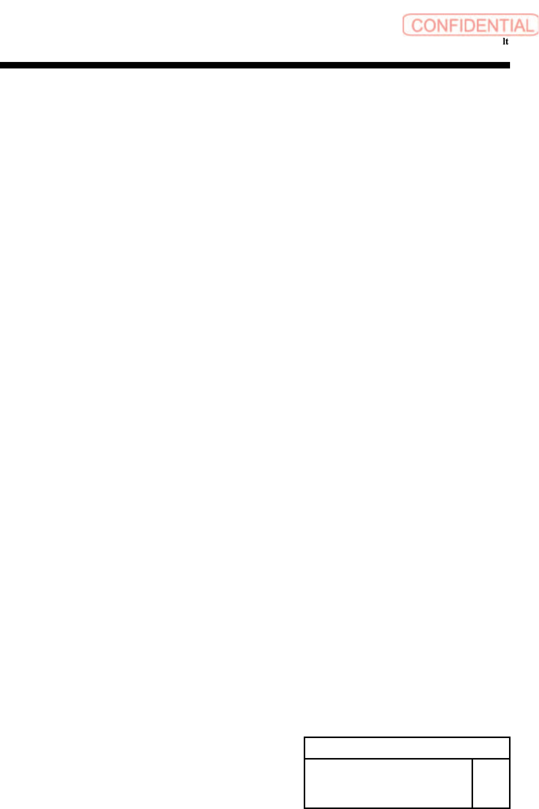
1 For the removal procedure for the head unit refer to
RPGB-10301-1
The following procedure is designed for the work on the
head block.
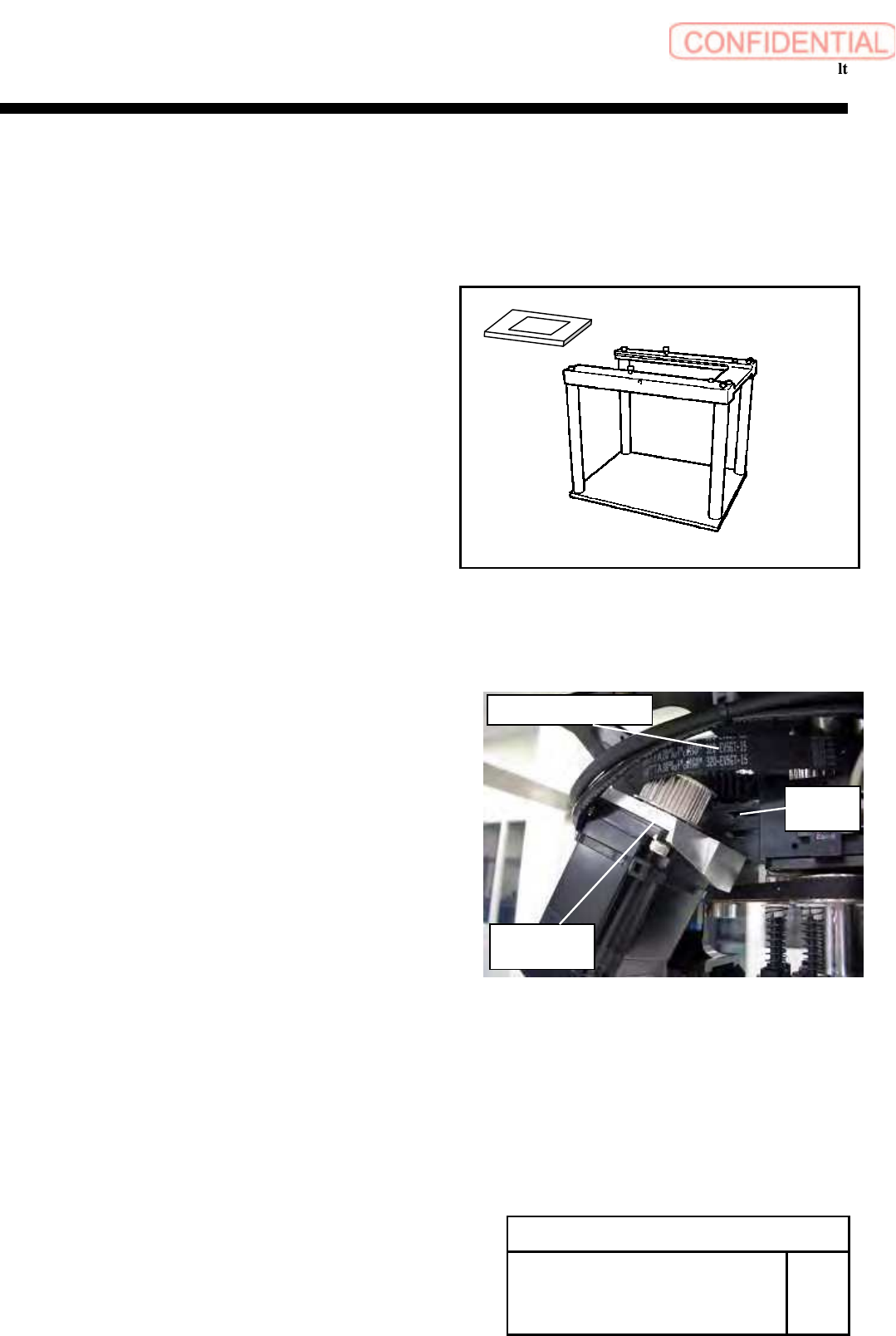
2 Remove the screws (2-C4x18), tilt the RT axis motor bracket.
Refer to RPGB-10601-1 _ 5
3 Remove the RT axis timing belt from the pulley on the motor side.
Change Procedure for RT-axis
Timing Belt
SHEET
1/3
RPGB-10901-1
RT Axis motor
bracket
C
4
x
18
W4
RT Axis timing belt
Change Procedure for RT axis Timing Belt
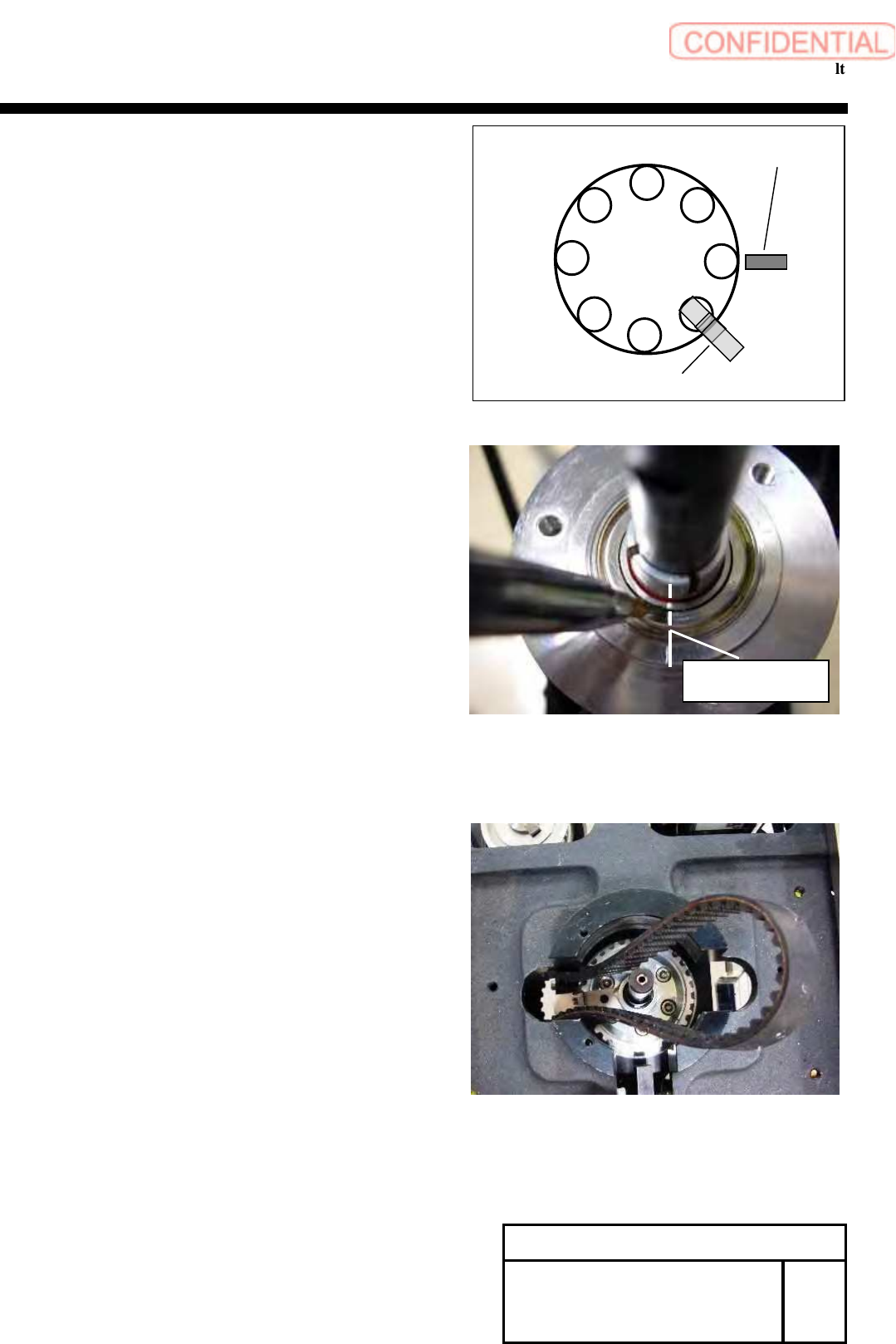
4 Remove the rotary encoder. Refer to RPGB-10701-1
1. Adjust the position as shown in figure.
2. Apply marking –off line to the encoder.
5
Take out the timing belt from upper side of
the head base.
Change Procedure for RT-axis
Timing Belt
SHEET
2/3
RPGB-10901-1
Marking
-
off line
Line
RT dog
RT ORG sensor
1
8
7
6
5
4
3
2