MAN00000772_SI-G200BB_SVCPDFA.pdf - 第686页
Chan g e Procedu re for RT-a xi s Timing Belt [Reassembl y] 6 Install the ne w timin g belt f rom upper side of the he ad base. 7 Attach the ro tary e ncode r. 1. Ref e r to RPGB-10701- 1 8 Apply the R T ax is timing be …
Change Procedure for RT axis Timing Belt
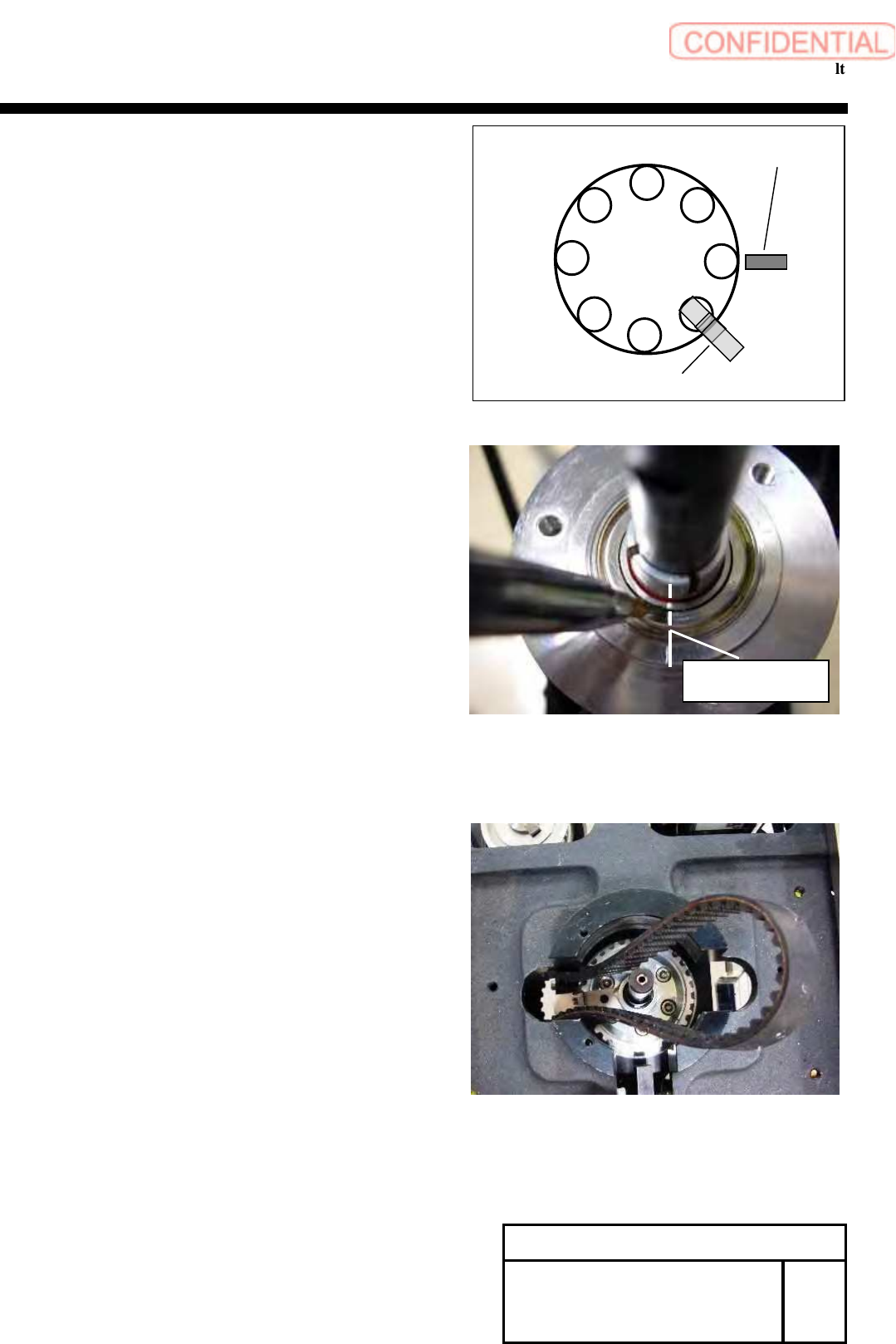
4 Remove the rotary encoder. Refer to RPGB-10701-1
1. Adjust the position as shown in figure.
2. Apply marking –off line to the encoder.
5
Take out the timing belt from upper side of
the head base.
Change Procedure for RT-axis
Timing Belt
SHEET
2/3
RPGB-10901-1
Marking
-
off line
Line
RT dog
RT ORG sensor
1
8
7
6
5
4
3
2
Change Procedure for RT-axis Timing
Belt
[Reassembly]
6 Install the new timing belt from upper side of the head base.
7 Attach the rotary encoder.
1. Refer to RPGB-10701-1
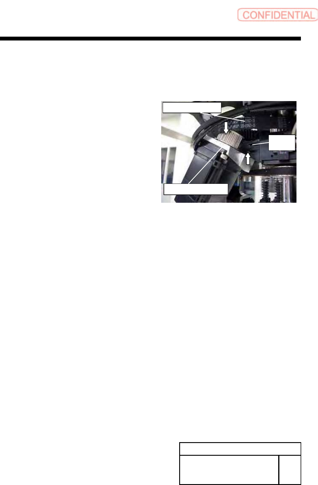
8 Apply the RT axis timing belt to the pulley on the motor side.
9 Temporarily tighten with the screws (2-C4x18) from the
rear side the H axis motor bracket.
10 Adjust the belt tension.
Refer to PGB-10601-1.
11 Install the head unit to the main body.
Refer to PGB-10301-1
[Adjustment]
12
Calibration
1.HLGB-10201-01 Machine Setup
2.HLGB-10304-01 Calibration
Change Procedure for RT-axis
Timing Belt
SHEET
3/3
RPGB-10901-1
RT axis Motor Bracket
C
4
x
18
W4
RT axis Timing Belt
Change Procedure for H Axis Motor Unit
Change Procedure for H Axis Motor Unit
[Necessary Jigs]
Dial gauge
Magnet Stand
[Disassembly]
1 Open the front and rear slide doors.
2
Push the head base to the center.
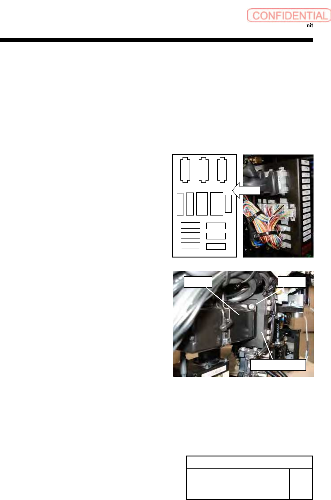
3 Cut the cable tie locking the wiring near the head unit
on the front side of the main body.
4 Remove the power connector (HM) and the encoder
connector (HE) from the connector plate.
5 Remove the screws (2-C4x10), and remove the H axis motor
from the H axis motor plate.
Change Procedure for H-axis
Motor
Unit
RPGB-11001-1
SEET
1/2
H motor
C4x10
H axis motor plate
CSFT
FSEN2
LED
PD
CSFT-LS
HM
RTM
RNM
HE VAC-2
RTS
RNE
RTE
Layout