MAN00000772_SI-G200BB_SVCPDFA.pdf - 第688页
Ch ange Procedu re for H Axis Moto r U n i t 6 Loo sen the screw (C3x 8), and remo ve the pinio n ge ar. 7 Remov e the power cable and the e nco der c able. [Reassembl y] 8 Conne ct the po w e r co nnector( HM) and the e…
Change Procedure for H Axis Motor Unit
Change Procedure for H Axis Motor Unit
[Necessary Jigs]
Dial gauge
Magnet Stand
[Disassembly]
1 Open the front and rear slide doors.
2
Push the head base to the center.
3 Cut the cable tie locking the wiring near the head unit
on the front side of the main body.
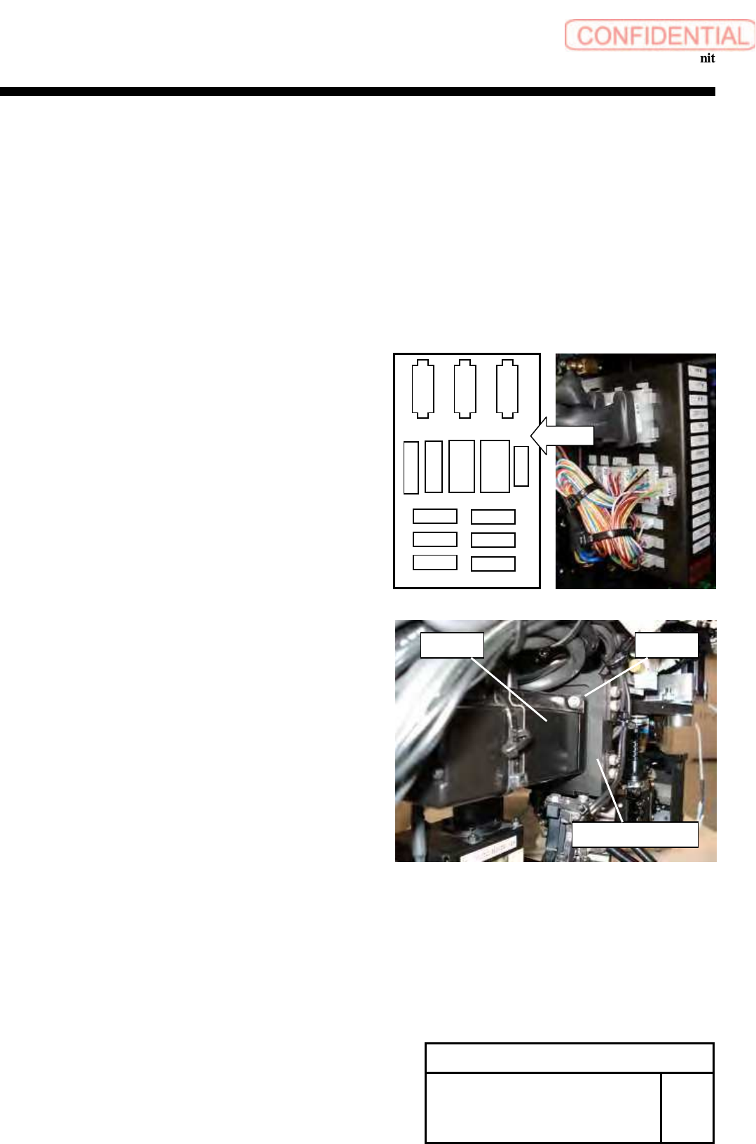
4 Remove the power connector (HM) and the encoder
connector (HE) from the connector plate.
5 Remove the screws (2-C4x10), and remove the H axis motor
from the H axis motor plate.
Change Procedure for H-axis
Motor
Unit
RPGB-11001-1
SEET
1/2
H motor
C4x10
H axis motor plate
CSFT
FSEN2
LED
PD
CSFT-LS
HM
RTM
RNM
HE VAC-2
RTS
RNE
RTE
Layout
Change Procedure for H Axis Motor Unit
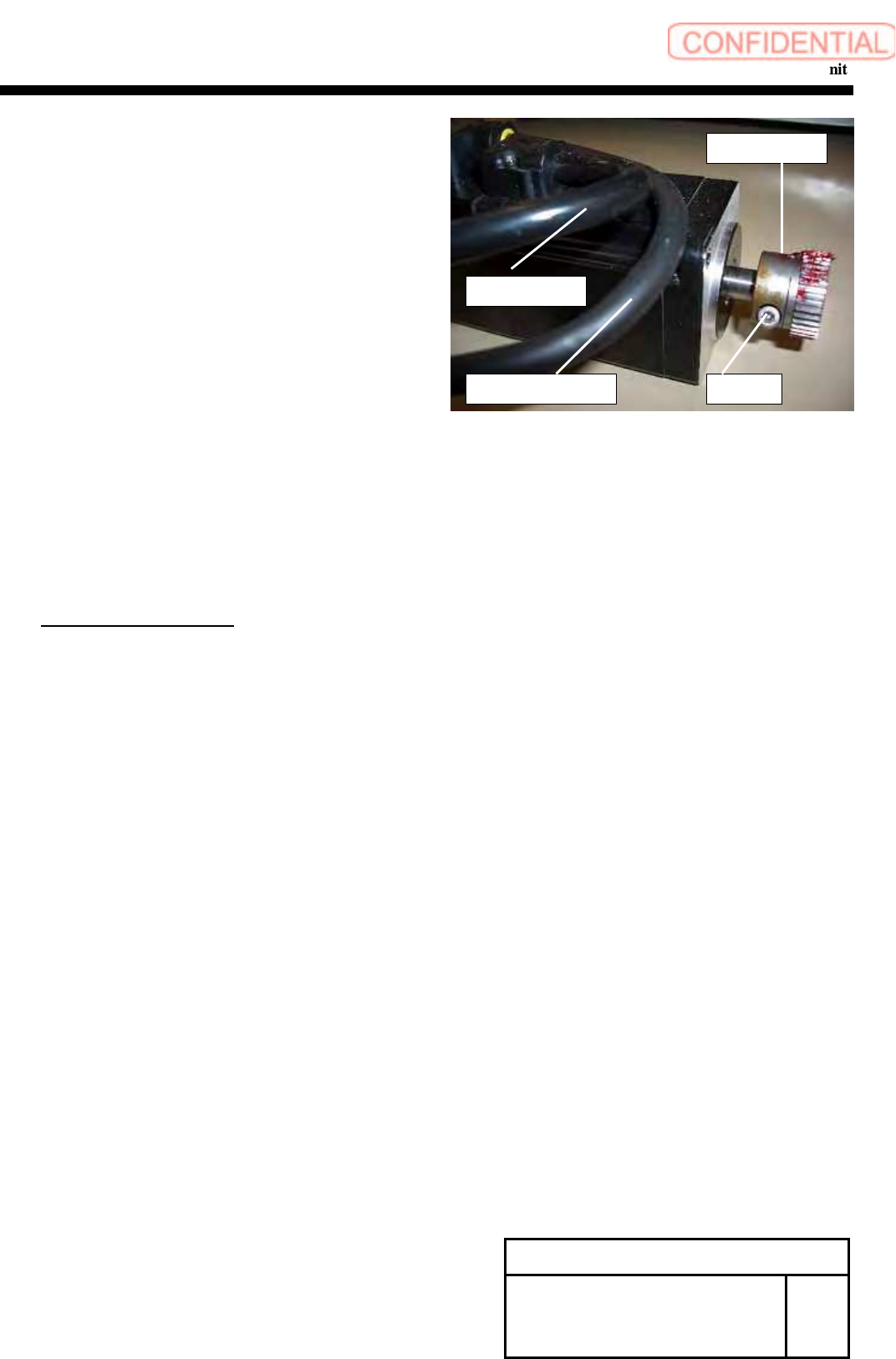
6
Loosen the screw (C3x8), and remove the pinion gear.
7 Remove the power cable and the encoder cable.
[Reassembly]
8 Connect the power connector(HM) and the encoder connector(HE)
to the new motor.
9 Attach the pinion gear by temporarily tighten with screw (C3x8).
POINT
Positioning is executed later.
10 Apply Locktite 242 to the screws (2-C4x10), apply H axis motor to
the H axis base plate, and fasten the screws for locking.
11 Connect the power connector (HM) and the encoder connector (HE)
of the motor, and lock the wiring with cable tie not to allow the wiring
to interfere with the movable parts.
[Adjustment]
12 Mechanical Adjustment
1.HLGB-10403-01 H Axis gear Z phase adjustment
13 Calibration
1.HLGB-10202-01 Setup
2.HLGB-10304-01 Calibration
Change Procedure for H-axis
Motor Unit
RPGB-11001-1
SEET
2/2
C3x8
Pinion Gear
Encoder Cable
Power Cable
Change Procedure for Lever Assembly of Head Unit
Change Procedure for Lever Assembly of Head Unit
[Necessary Jigs]
Dial Gage
Magnet Stand
7mm wrench
[Disassembly]
1 Turn off the main power and air main cock.
2
Open the front slide door.
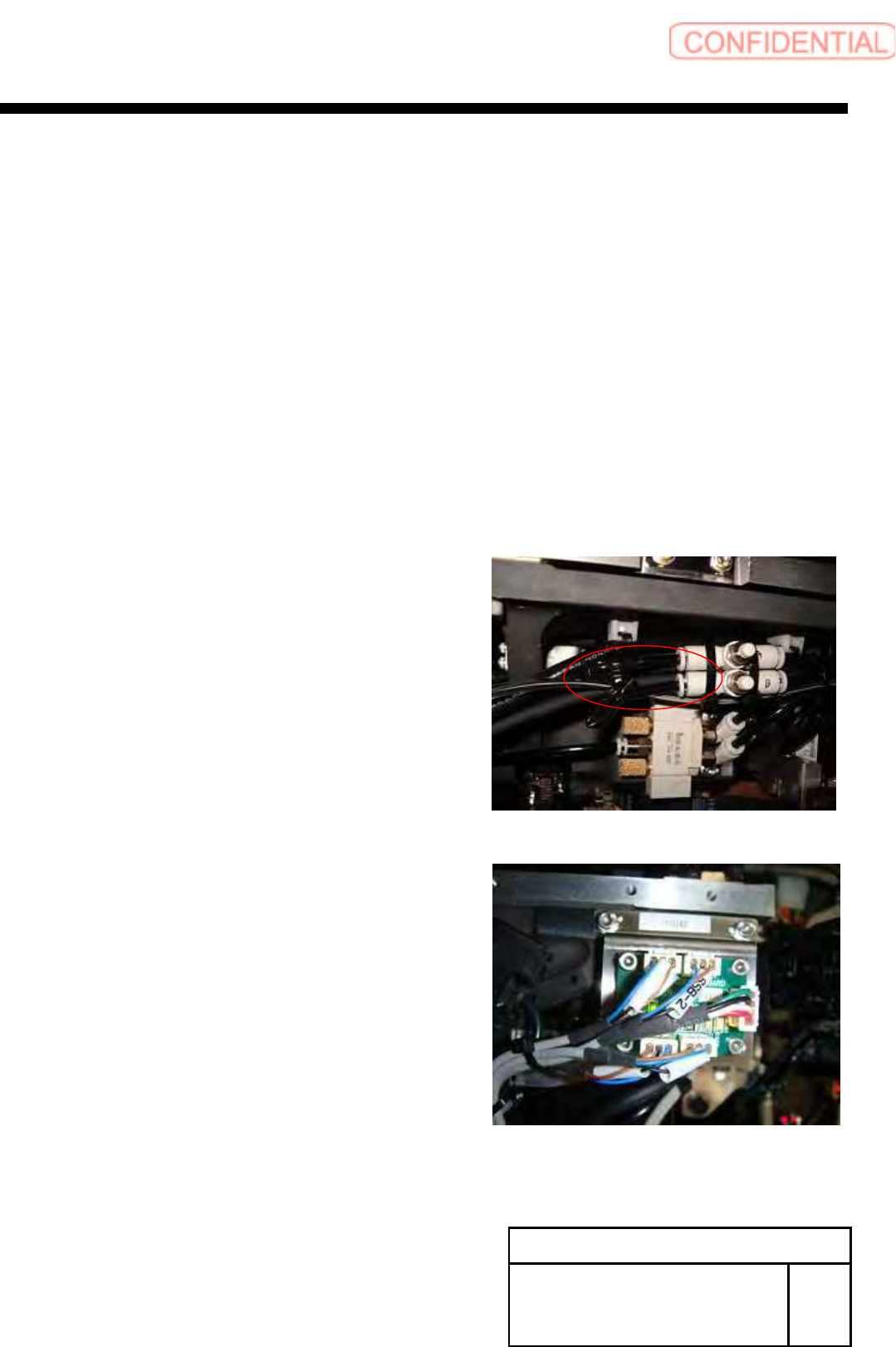
3 Remove the detection camera Assy.
1. Pull out the air tube of rear of HEAD.
2.SSB-2 and SSB-4 connectors pull out from the SSB board at
side of head.
POINT
Cut the cable tie from SSB-2 and SSB-4 cables.
Change Procedure for Head Unit
Lever Assembly
SHEET
1/7
RPGB-11101-1