MAN00000772_SI-G200BB_SVCPDFA.pdf - 第689页
Ch ange Procedu re fo r Lever A ssembly o f Head Un it Change Pro cedure fo r Lever Ass em bly of Head Unit [Necess a r y Jigs] Dial Gage Magnet Stand 7mm wre nch [Disassembly] 1 T urn off the main po wer and air main c …
Change Procedure for H Axis Motor Unit
6
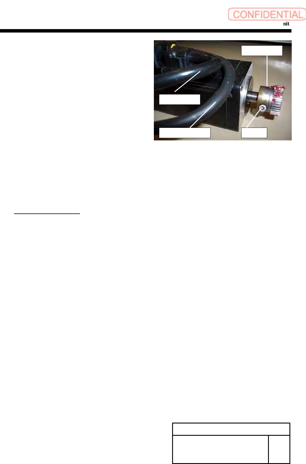
Loosen the screw (C3x8), and remove the pinion gear.
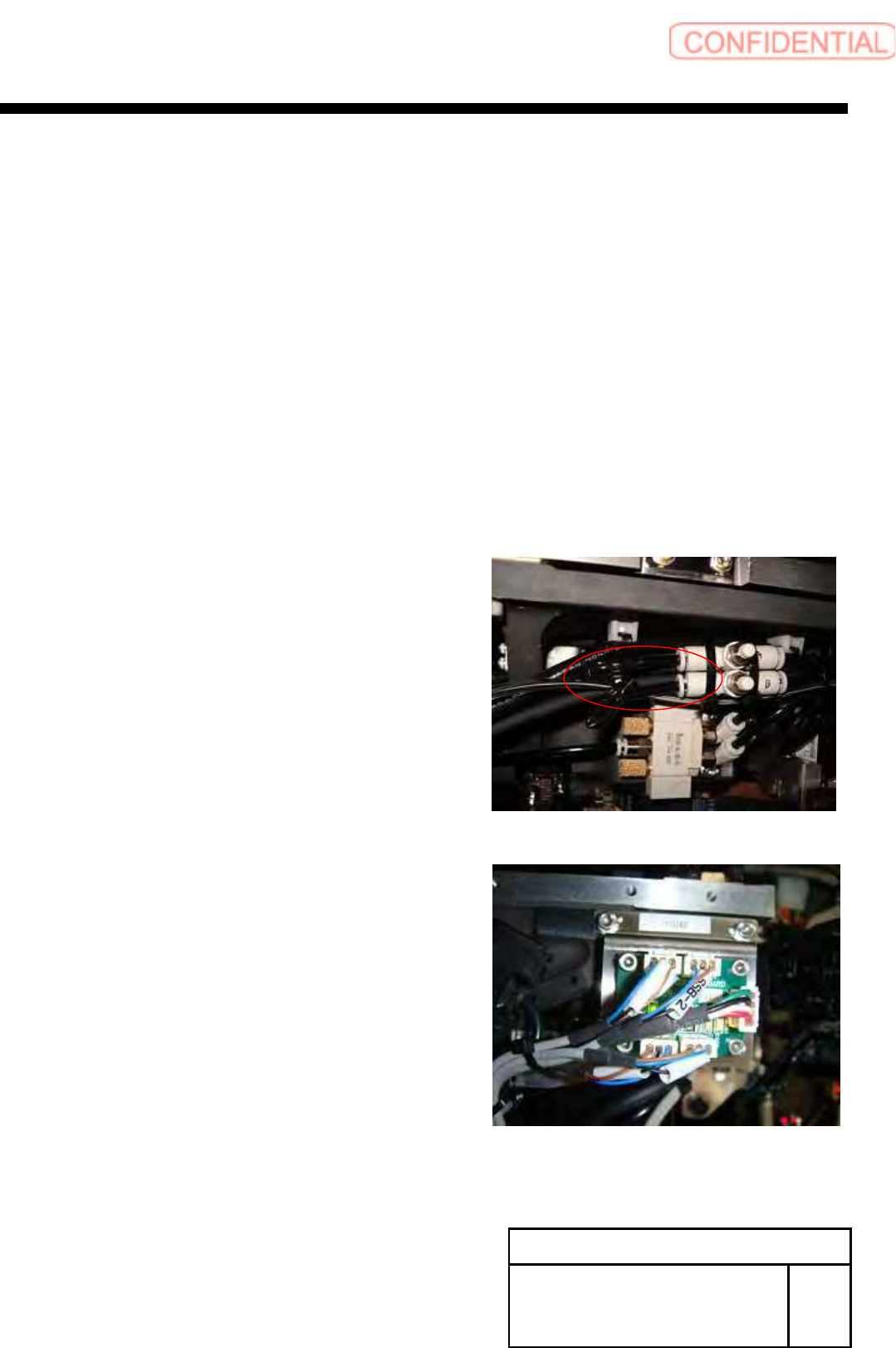
7 Remove the power cable and the encoder cable.
[Reassembly]
8 Connect the power connector(HM) and the encoder connector(HE)
to the new motor.
9 Attach the pinion gear by temporarily tighten with screw (C3x8).
POINT
Positioning is executed later.
10 Apply Locktite 242 to the screws (2-C4x10), apply H axis motor to
the H axis base plate, and fasten the screws for locking.
11 Connect the power connector (HM) and the encoder connector (HE)
of the motor, and lock the wiring with cable tie not to allow the wiring
to interfere with the movable parts.
[Adjustment]
12 Mechanical Adjustment
1.HLGB-10403-01 H Axis gear Z phase adjustment
13 Calibration
1.HLGB-10202-01 Setup
2.HLGB-10304-01 Calibration
Change Procedure for H-axis
Motor Unit
RPGB-11001-1
SEET
2/2
C3x8
Pinion Gear
Encoder Cable
Power Cable
Change Procedure for Lever Assembly of Head Unit
Change Procedure for Lever Assembly of Head Unit
[Necessary Jigs]
Dial Gage
Magnet Stand
7mm wrench
[Disassembly]
1 Turn off the main power and air main cock.
2
Open the front slide door.
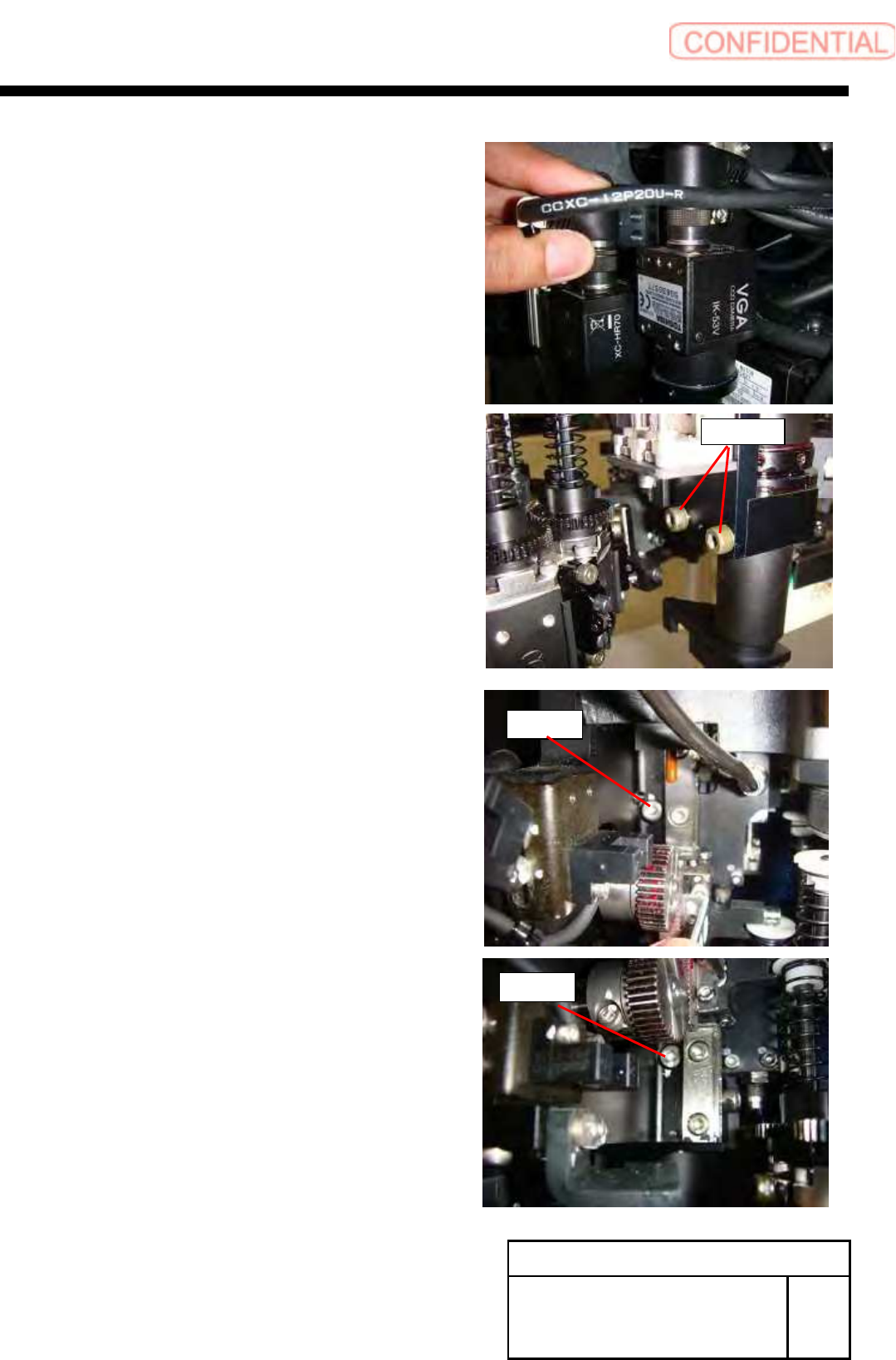
3 Remove the detection camera Assy.
1. Pull out the air tube of rear of HEAD.
2.SSB-2 and SSB-4 connectors pull out from the SSB board at
side of head.
POINT
Cut the cable tie from SSB-2 and SSB-4 cables.
Change Procedure for Head Unit
Lever Assembly
SHEET
1/7
RPGB-11101-1
Change Procedure for Lever Assembly of Head Unit
3. Pull out the connector (cam2-U*) of camera cable,
loosen 2-CP4x8, and remove the detection camera.
4. Loosen 2-CP4x6 from the back of the head.
Change Procedure for Head Unit
Lever Assembly
SHEET
2/7
RPGB-11101-1
CP4x8
CP4x6
CP4x6