MAN00000772_SI-G200BB_SVCPDFA.pdf - 第694页
Ch ange Procedu re fo r Head Un it Leve r Asse m b l y 13 Adjust the g ap betwe en the rack and the gear. 1. T u r n on the main po wer and the air main co c k. C AUT ION Do no t perfo rm ori gin retur n. 2. Adj ust the …
Change Procedure for Head Unit Lever Assembly
[Reassembly]
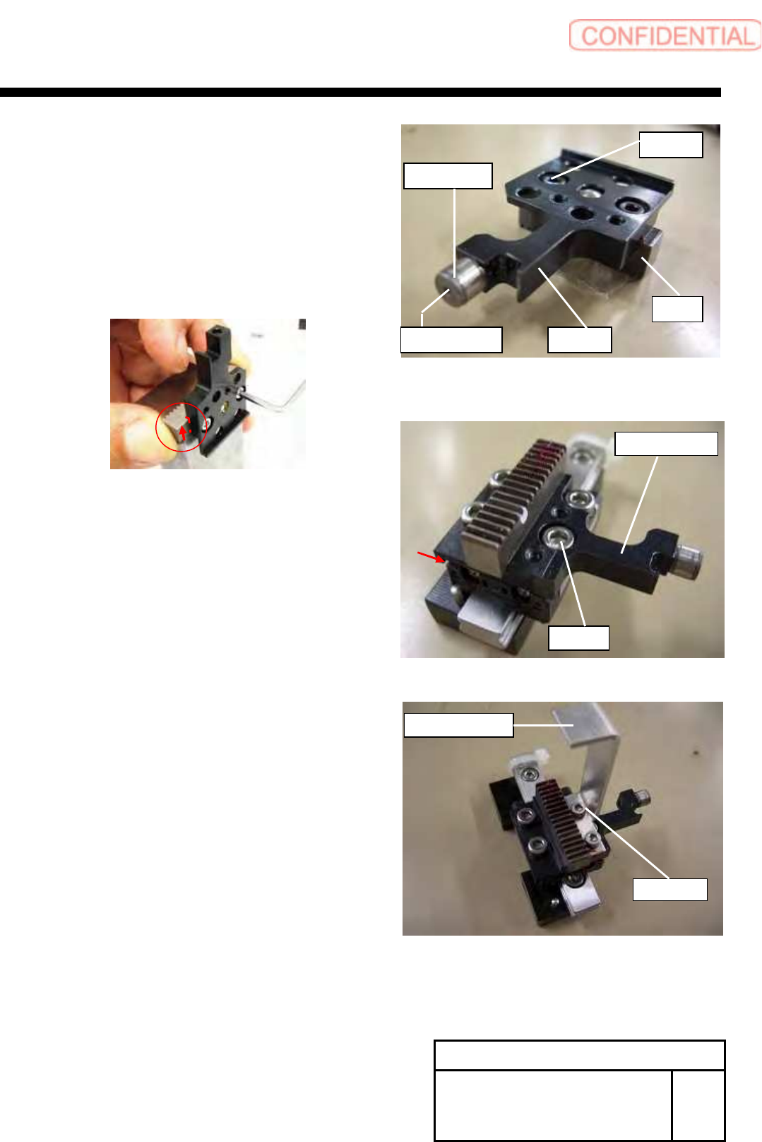
8 Install the Cam-follower to the new lever
1.Apply locktite 242 to the part of the screw.
Tighten from the tightening hole with the wrench.
9 Apply locktite 242 to the screws (2-C2.5x4).
Attach the rack to the new lever assembly
and tighten the screws.
POINT
Attach the rack while touch to the lever.
10 Apply the Locktite 242 to the screws (4-C3x4),
attach the lever assy to the LM guide.
POINT
Attach the lever assy while touch in the direction of arrow.
Refer to figure.
11
Apply the Locktite 242 to the screws (2-C2.5x5)
attach the H axis sensor dog to the lever assembly,
tighten the screws.
12 Attach the rail holder to the H axis motor bracket,
tighten the screws (2-C4x16).
Change Procedure for Head Unit
Lever Assembly
SHEET
5/7
RPGB-11101-1
C2.5×4
Rack
lever
Cam-follower
Tightening hole
C2.5
x
5
H axis sensor dog
C3x4
Lever Assy
C
レ
Change Procedure for Head Unit Lever Assembly
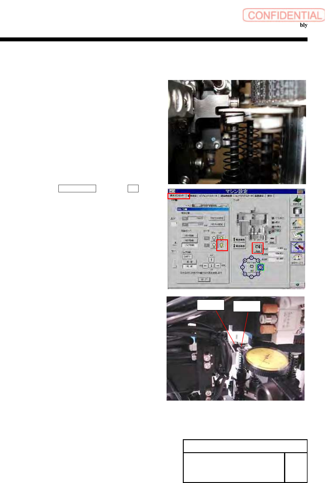
13 Adjust the gap between the rack and the gear.
1. Turn on the main power and the air main cock.
CAUTION
Do not perform origin return.
2. Adjust the position of lever and inner shaft.
3. Click in order of ORG OFFSET tab, push the R.H. button.
RN/H axis screen is displayed.
4. Turns on, only H axis of servo.
5
. The dial gauge touch on the lever then make sure the gap.
POINT
Set the dial gauge from the rear of the head.
6. Down the H axis, -22mm by relative movement.
Confirm the gap by dial gauge.
Specification
Gap of upper end, lower end 0.01mm~0.03mm
Gap of upper end – Gap of lower end within=0.01mm
7.Adjust the rail holder again when it is the out of specification.
POINT
After complete the adjustment, remove a screw (C4x16)
then apply the Locktite 242, tighten the screw.
Repeat the another screw.
Change Procedure for Head Unit
Lever Assembly
SHEET
6/7
RPGB-11101-1
Lever
Dial Gauge
Change Procedure for Head Unit Lever Assembly
14 Attach the pickup check camera up/down cylinder.
1. Turn off the main power.
2. Attach it by reverse order of disassembly.
[Adjustment]
15 Setup
1.HLGB-10403-01 H Axis gear Z phase adjustment
16 Calibration
1.HLGB-10202-01 Setup
2.HLGB-10304-01 Calibration
Change Procedure for Head
Unit Lever Assembly
RPGB-11101-1
SEET
7/7