MAN00000772_SI-G200BB_SVCPDFA.pdf - 第695页
Ch ange Procedu re fo r Head Un it Leve r Asse m b l y 14 Attach the pickup c hec k c amera up/do wn cy linder. 1. T ur n off the main powe r. 2. Attach it by reverse o rder of disassembly . [Adju s tment] 15 Set up 1.HL…
Change Procedure for Head Unit Lever Assembly
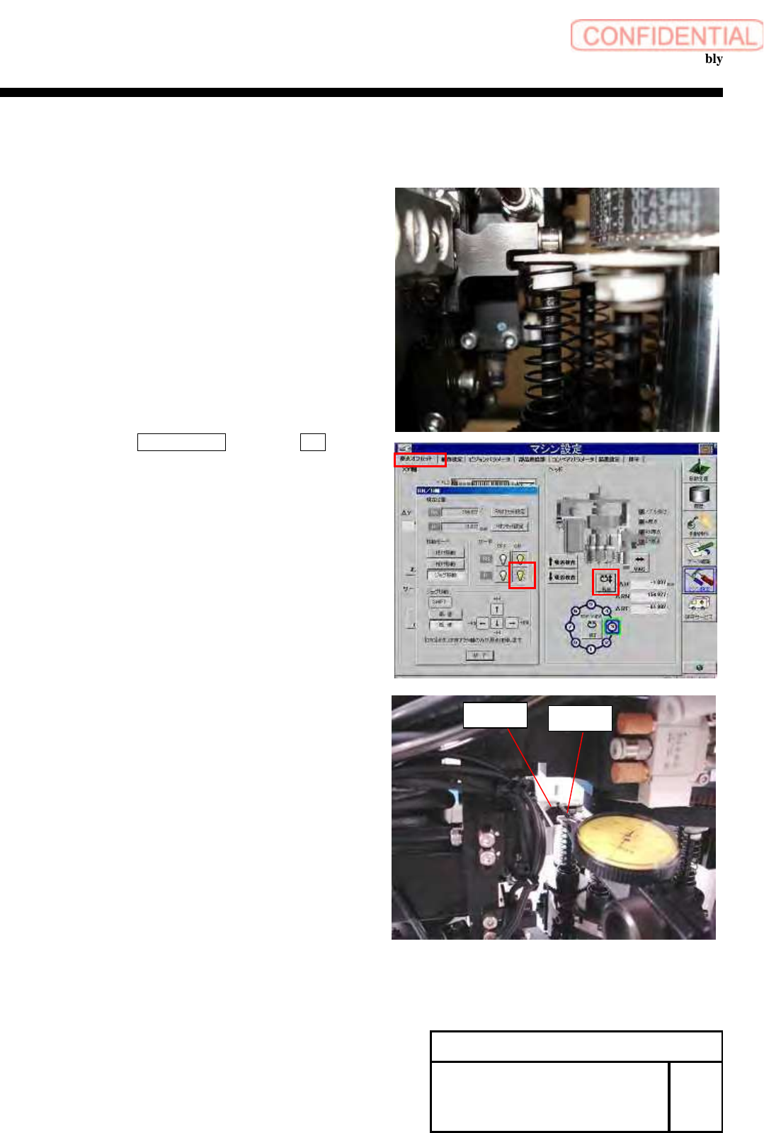
13 Adjust the gap between the rack and the gear.
1. Turn on the main power and the air main cock.
CAUTION
Do not perform origin return.
2. Adjust the position of lever and inner shaft.
3. Click in order of ORG OFFSET tab, push the R.H. button.
RN/H axis screen is displayed.
4. Turns on, only H axis of servo.
5
. The dial gauge touch on the lever then make sure the gap.
POINT
Set the dial gauge from the rear of the head.
6. Down the H axis, -22mm by relative movement.
Confirm the gap by dial gauge.
Specification
Gap of upper end, lower end 0.01mm~0.03mm
Gap of upper end – Gap of lower end within=0.01mm
7.Adjust the rail holder again when it is the out of specification.
POINT
After complete the adjustment, remove a screw (C4x16)
then apply the Locktite 242, tighten the screw.
Repeat the another screw.
Change Procedure for Head Unit
Lever Assembly
SHEET
6/7
RPGB-11101-1
Lever
Dial Gauge

Change Procedure for Head Unit Lever Assembly
14 Attach the pickup check camera up/down cylinder.
1. Turn off the main power.
2. Attach it by reverse order of disassembly.
[Adjustment]
15 Setup
1.HLGB-10403-01 H Axis gear Z phase adjustment
16 Calibration
1.HLGB-10202-01 Setup
2.HLGB-10304-01 Calibration
Change Procedure for Head
Unit Lever Assembly
RPGB-11101-1
SEET
7/7
XY axis movable parts
RPGB-11201-01
Change Procedure for
X Axis
LM-GUIDE
SEET
1/7
Change Procedure for X Axis LM-guide
[Necessary jigs]
■ Hold JIG
■ Thickness gauge ( 0.02mm)
■ Grease gun
■ Head block
■
Assembly plate
CAUTION
LM-guide is 1set in 2rail. (Basis side and Subordinate side)
Basis side and Subordinate side Exchange together at every time
[Disassembly of LM-guide]
1, Prior work
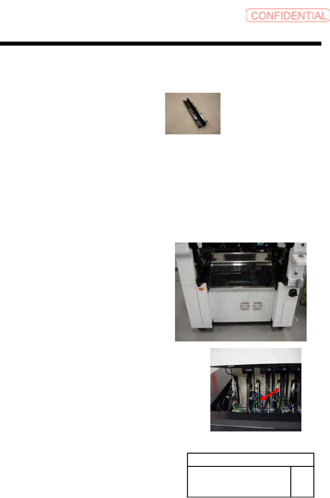
1-1 Remove the Cassette bank changer of M/C
1-2 Stop the M/C. turn off the power switch
1-3 Remove the Shooter cover
1-4 X-Axis move to Y-Axis end position
POINT
Head position move to center of X-axis
1-5
Remove the X-axis motor power connector (XM)