MAN00000772_SI-G200BB_SVCPDFA.pdf - 第696页
XY axis movable parts RPGB-1 1201-01 Change Proce dure for X Axi s LM-GUIDE SEET 1 / 7 Change Procedure for X Axis LM-guide [Necessary jigs] ■ Hold JIG ■ Thickness gauge ( 0.02mm) ■ Grease gun ■ Head bloc k ■ Assembly pl…
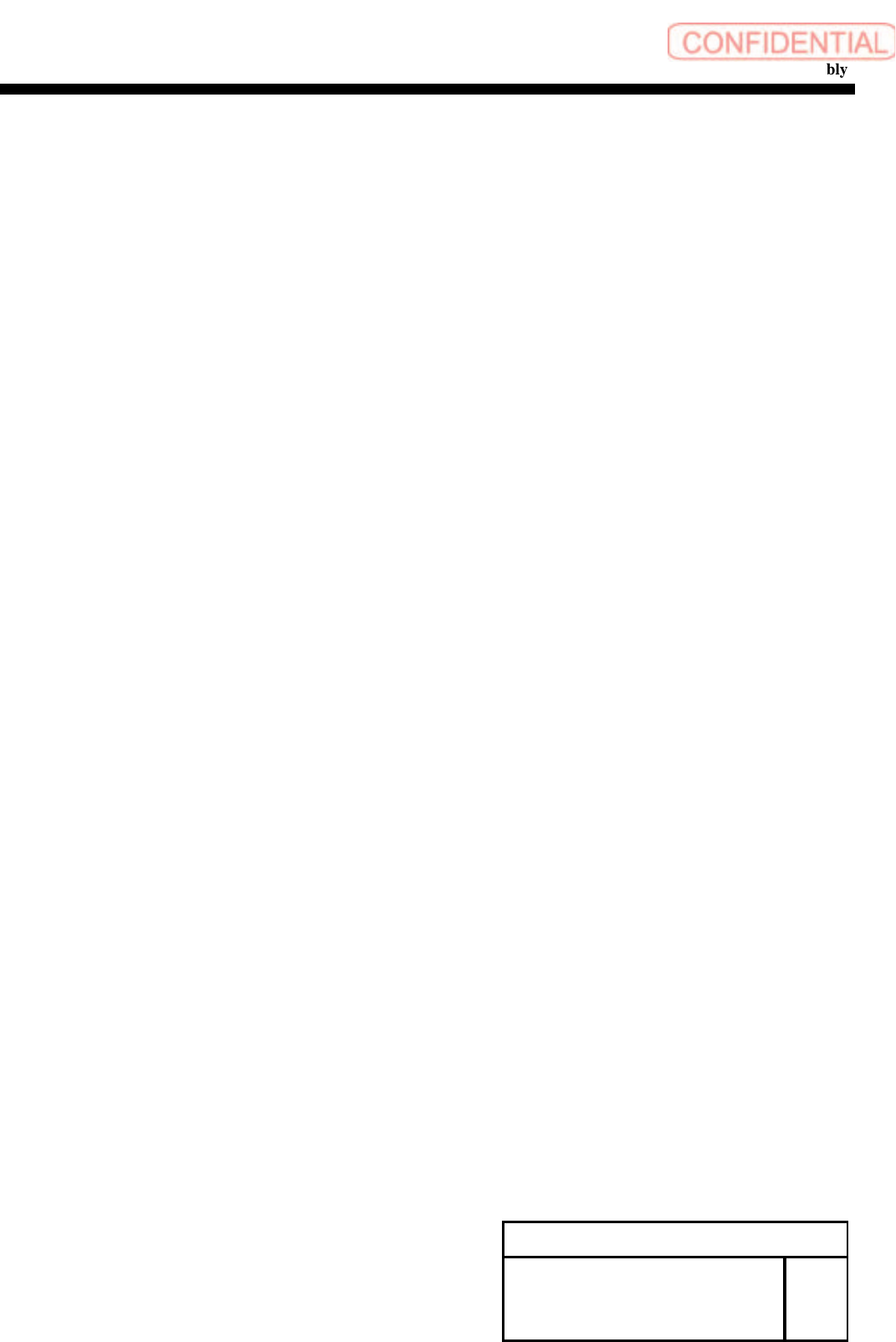
Change Procedure for Head Unit Lever Assembly
14 Attach the pickup check camera up/down cylinder.
1. Turn off the main power.
2. Attach it by reverse order of disassembly.
[Adjustment]
15 Setup
1.HLGB-10403-01 H Axis gear Z phase adjustment
16 Calibration
1.HLGB-10202-01 Setup
2.HLGB-10304-01 Calibration
Change Procedure for Head
Unit Lever Assembly
RPGB-11101-1
SEET
7/7
XY axis movable parts
RPGB-11201-01
Change Procedure for
X Axis
LM-GUIDE
SEET
1/7
Change Procedure for X Axis LM-guide
[Necessary jigs]
■ Hold JIG
■ Thickness gauge ( 0.02mm)
■ Grease gun
■ Head block
■
Assembly plate
CAUTION
LM-guide is 1set in 2rail. (Basis side and Subordinate side)
Basis side and Subordinate side Exchange together at every time
[Disassembly of LM-guide]
1, Prior work
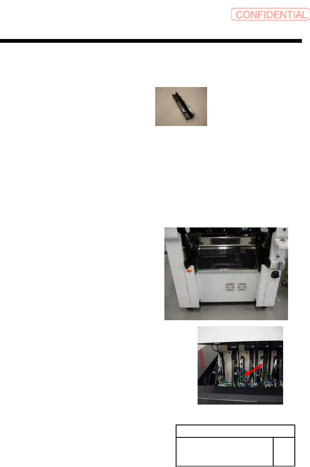
1-1 Remove the Cassette bank changer of M/C
1-2 Stop the M/C. turn off the power switch
1-3 Remove the Shooter cover
1-4 X-Axis move to Y-Axis end position
POINT
Head position move to center of X-axis
1-5
Remove the X-axis motor power connector (XM)
XY axis movable parts
RPGB-11201-01
Change Procedure for
X Axis
LM-GUIDE
SEET
2/7
2, Remove the Head Unit
Refer to the following
A-head RPF-10103-01
B-Head RPGB-10301-01
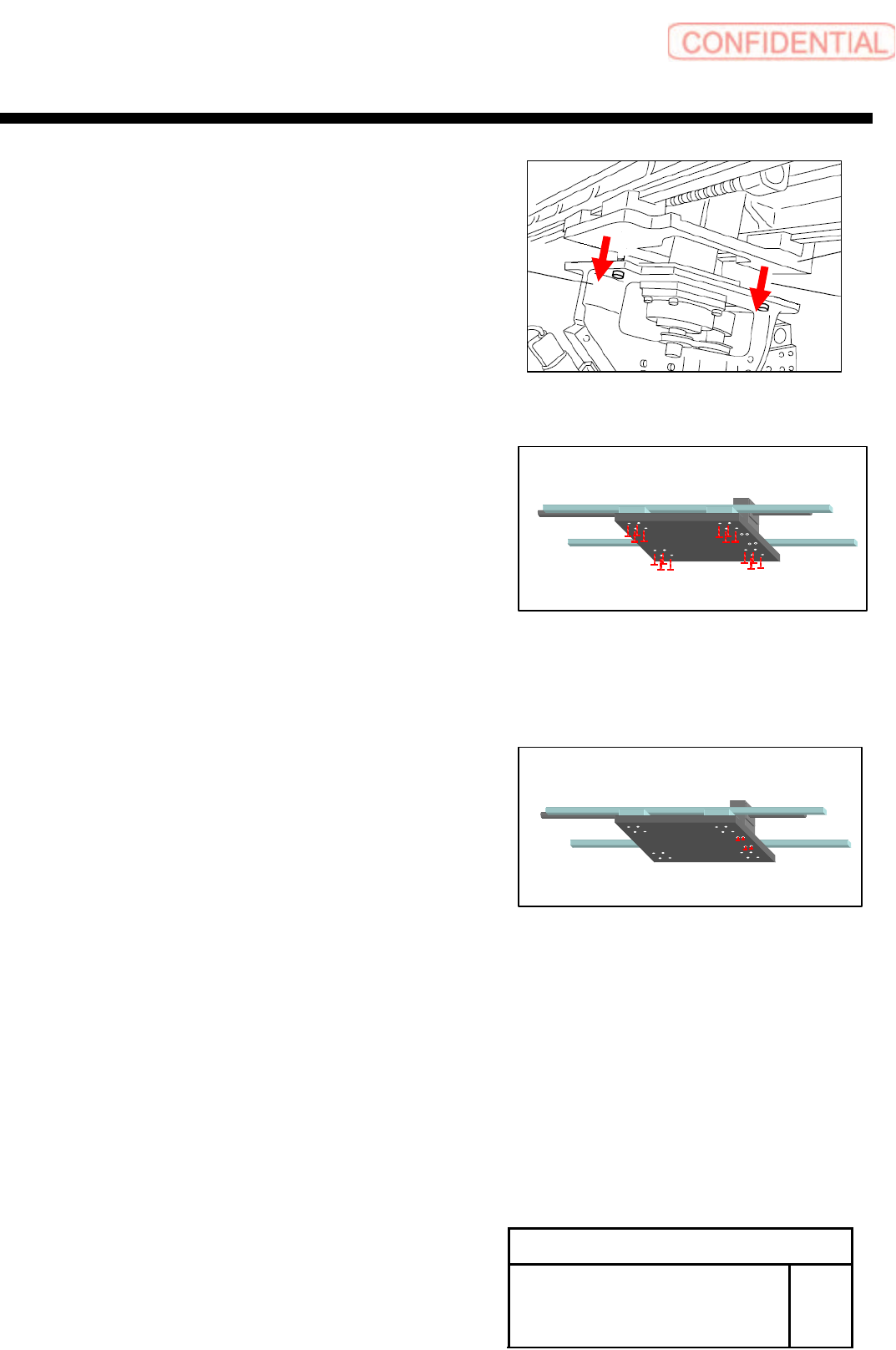
3, Fixed the screw in X-axis Base Saddle and slide block
of a LM-guide, unscrew it,
(Basis side and Subordinate side)
4, Fixed the screw in X-axis Base Saddle and nut holder
of a Y-axis ball screw, loosen it
POINT
Loosen it so that a X-axis Base Saddle
does not have tension
5, Remove the LM-guide
(Basis side and Subordinate side)