MAN00000772_SI-G200BB_SVCPDFA.pdf - 第702页
XY axis movable parts RPGB-1 1201-01 Change Proce dure for X Axi s LM-GUIDE SEET 7 / 7 12, Connect the X-axis moto r power connector (XM) 13, Installation the Head Unit; and setup & Calibration Refer to the fol lowin…
XY axis movable parts
RPGB-11201-01
Change Procedure for
X Axis
LM-GUIDE
SEET
6/7
10, Slide block and installation surface of
the X-axis Base Saddle tighten it
(Subordinate side LM-guide)
POINT
Confirm Motion smoothly when move
X-axis back and forth
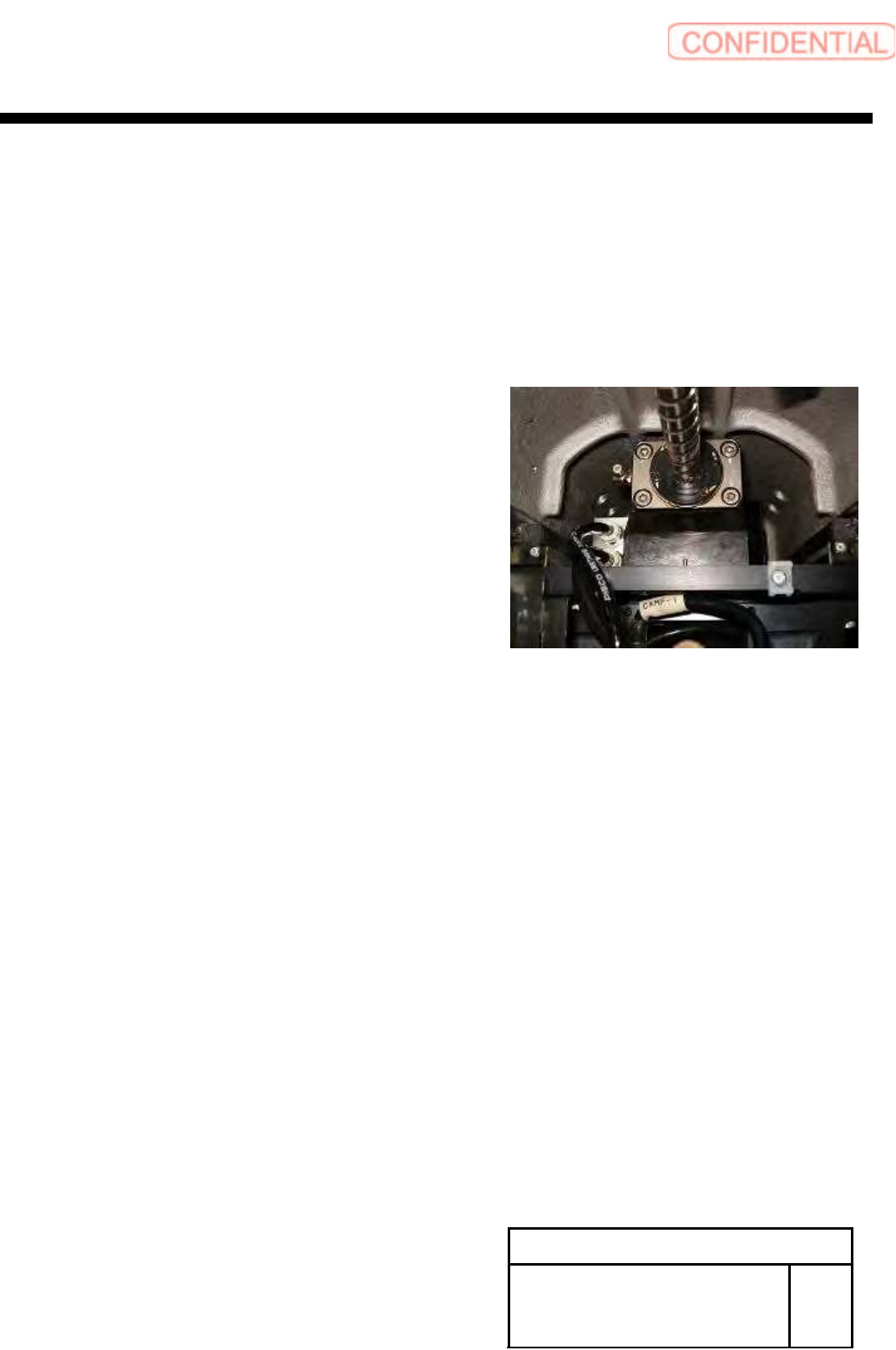
11, Confirm the position of X axis Base Saddle,
2 – 3mm from the motor side of mechanical end
Then Install ball screw of nut folder to
the X-axis Base Saddle, tighten it
11-1 Push a nut holder to a positioning pin
and tighten a screw at the opposite angle
11-2 Loosen a screw fixing a nut holder and the nut
of the ball screw and close it at the opposite angle again
11-3 again 12-1
11-4 again 12-2
POINT
Confirm Motion smoothly when move
X-axis back and forth
XY axis movable parts
RPGB-11201-01
Change Procedure for
X Axis
LM-GUIDE
SEET
7/7
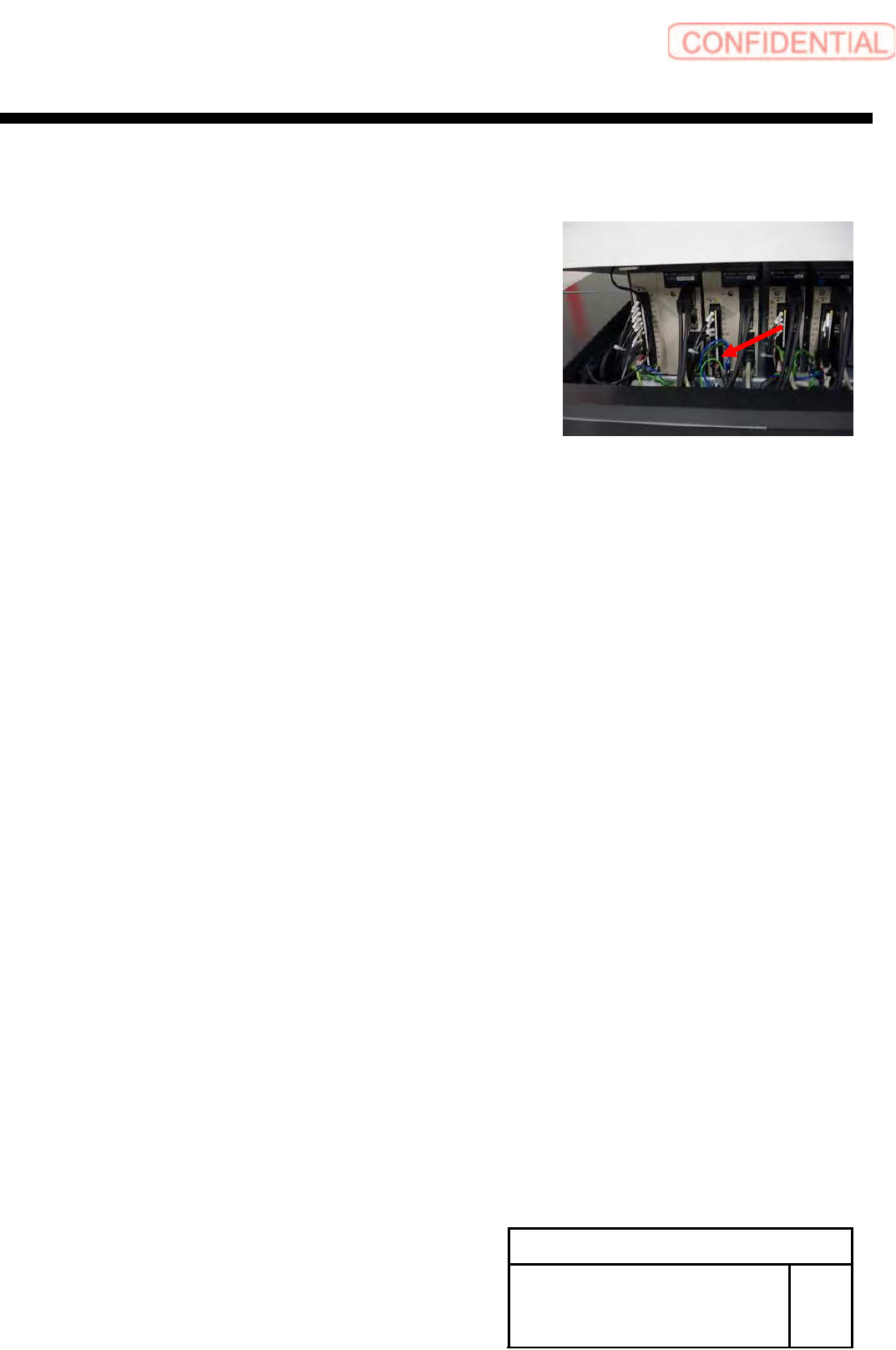
12, Connect the X-axis motor power connector (XM)
13, Installation the Head Unit;
and setup & Calibration
Refer to the following
A-head RPF-10103-01
B-Head RPGB-10301-01
XY axis movable parts
RPGB-11301-01
Change Procedure for
Y Axis
LM-GUIDE
SEET
1/9
Change Procedure for Y Axis LM-guide
[Necessary jigs]
■ Hold JIG
■ Thickness gauge (0.01mm, 0.02mm)
■ Grease gun
CAUTION
LM-guide is 1set in 2rail. (Right and Left)
Exchange of right and left at the same time
standard work is to exchange the LM guide of right and left one each by turns
Working operation is same time as FRONT side and REAR side
[Disassembly of LM-guide]
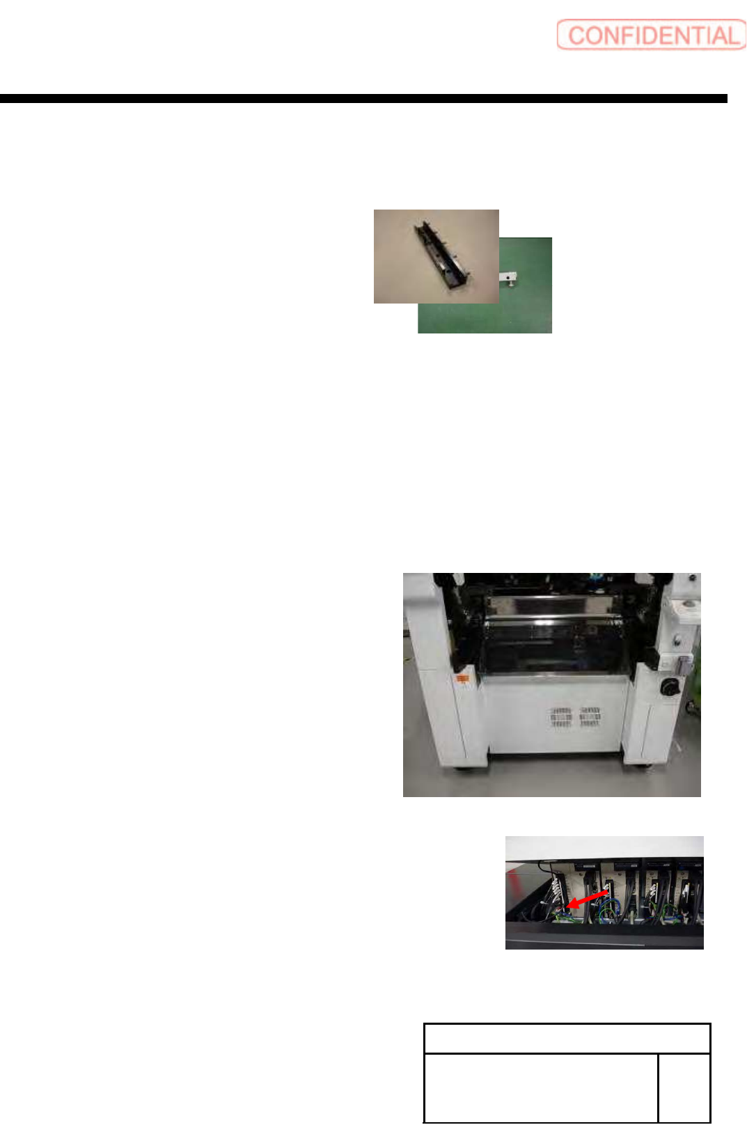
1, Prior work
1-1 Remove the Cassette bank chenger of M/C
1-2 Stop the M/C. turn off the power switch
1-3 Remove the Shooter cover
1-4 X-Axis move to Y-Axis end position
1-5
Remove the Y-axis motor power connector (YM)