MAN00000772_SI-G200BB_SVCPDFA.pdf - 第704页
XY axis movable parts RPGB-1 1301-01 Change Procedure for Y Axis LM-GUIDE SEET 2 / 9 2, Fixed the screw in X-axis and slide block of a LM-guide, unscrew it, (slide block of front side and rear side) POINT keep the balanc…
XY axis movable parts
RPGB-11301-01
Change Procedure for
Y Axis
LM-GUIDE
SEET
1/9
Change Procedure for Y Axis LM-guide
[Necessary jigs]
■ Hold JIG
■ Thickness gauge (0.01mm, 0.02mm)
■ Grease gun
CAUTION
LM-guide is 1set in 2rail. (Right and Left)
Exchange of right and left at the same time
standard work is to exchange the LM guide of right and left one each by turns
Working operation is same time as FRONT side and REAR side
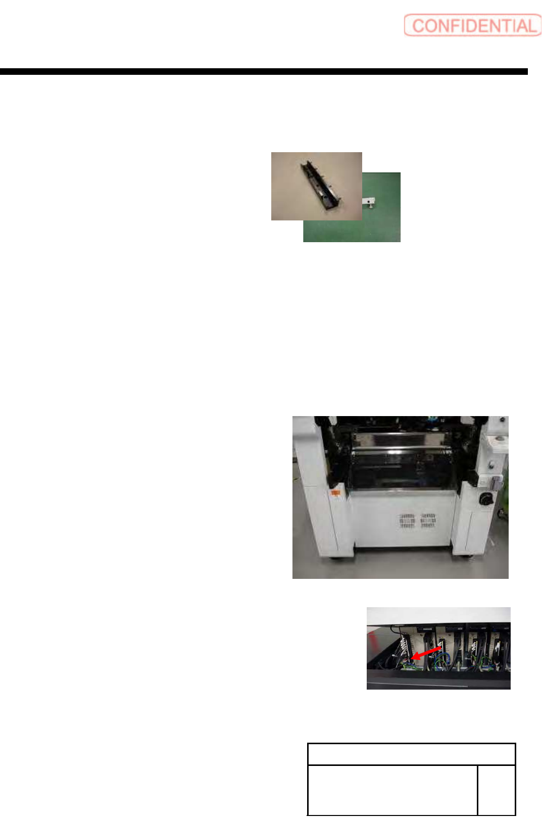
[Disassembly of LM-guide]
1, Prior work
1-1 Remove the Cassette bank chenger of M/C
1-2 Stop the M/C. turn off the power switch
1-3 Remove the Shooter cover
1-4 X-Axis move to Y-Axis end position
1-5
Remove the Y-axis motor power connector (YM)
XY axis movable parts
RPGB-11301-01
Change Procedure for
Y Axis
LM-GUIDE
SEET
2/9
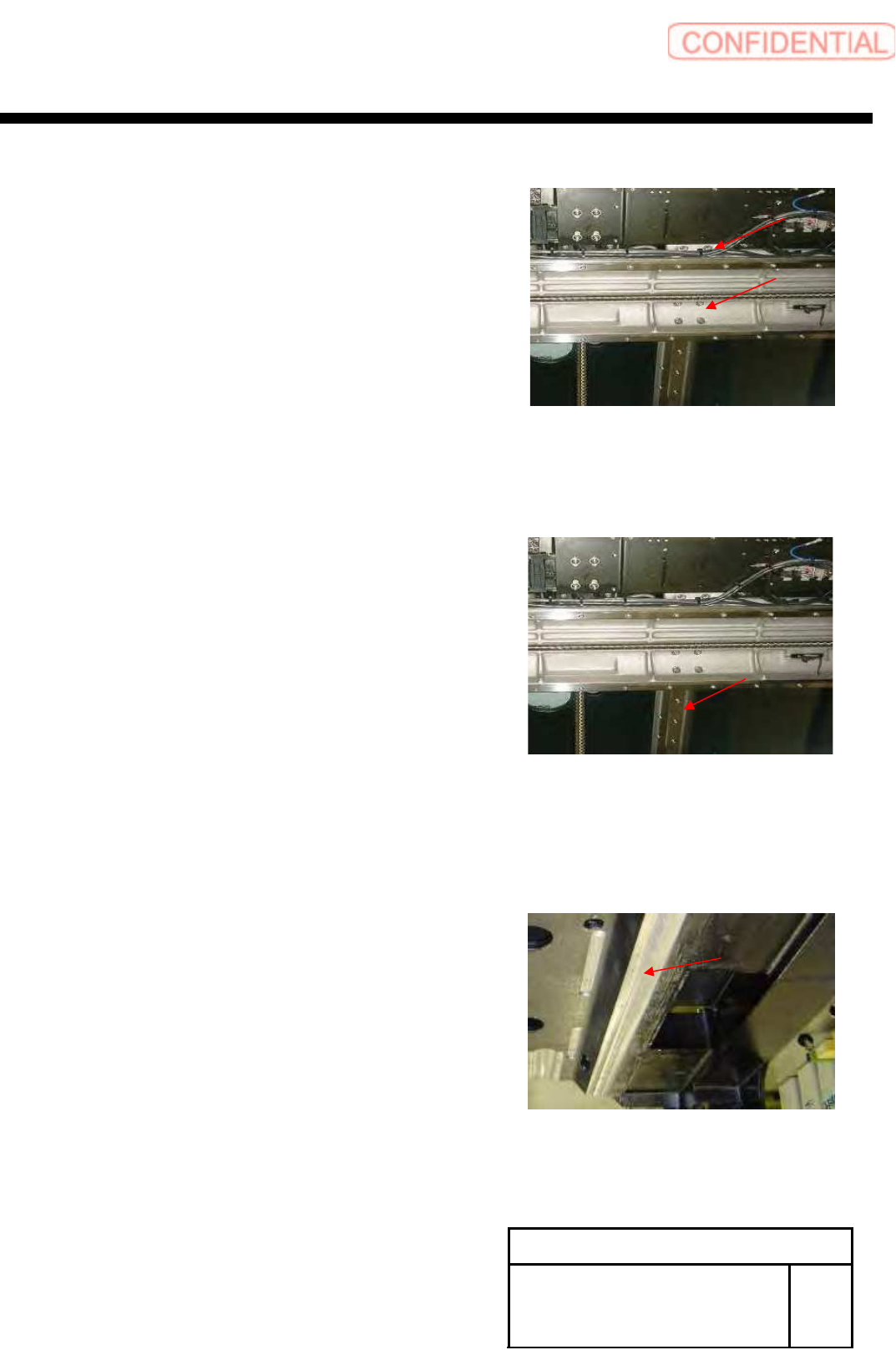
2, Fixed the screw in X-axis and slide block of
a LM-guide, unscrew it,
(slide block of front side and rear side)
POINT
keep the balance of the X-axis and let overweight to
ball screw reduce
Head position is move to the side that does not exchange
a LM guide is BEST
Do not remove right and left at the same time
Be careful not to drop a washer
3, Remove the LM-guide
(LM-guide of right and left)
[Reassembly of LM-guide]
1, Prior work
1-1 Apply grease into new LM-guide
POINT
Application grease (AFC-grease Maker: THK)
use a suitable amount
Be careful to not apply much quantity
Be careful of slide block come off and ball fall
1-2 Cleaning of the LM-guide installation surface
POINT
Polish an installation surface with an oil stone
Wipe dust at clean cloth
XY axis movable parts
RPGB-11301-01
Change Procedure for
Y Axis
LM-GUIDE
SEET
3/9
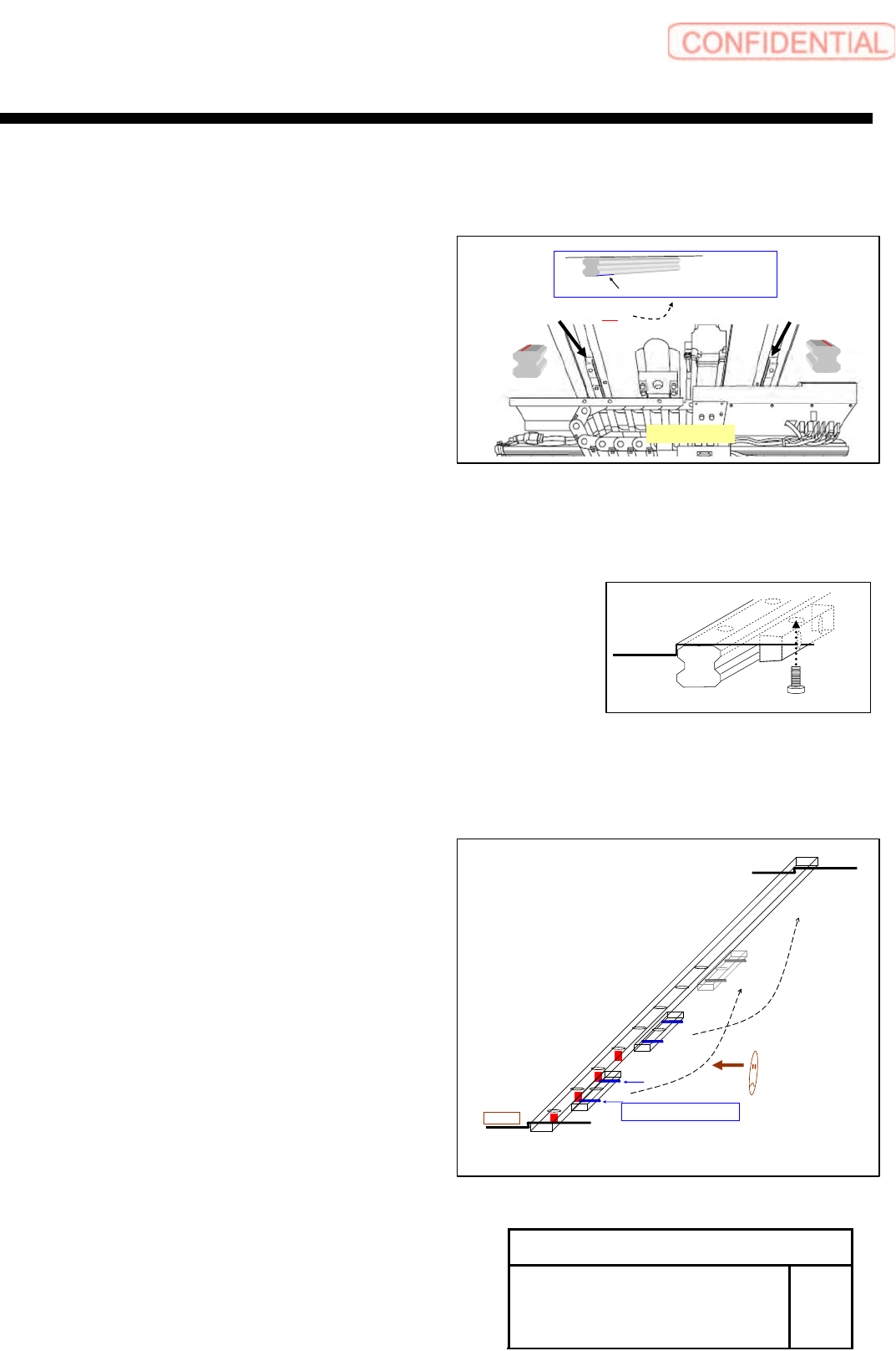
2, Install LM-guide and temporarily stop the screw
POINT
From M/C FRONT view
Left sides LM-guide have KB mark
Right side LM-guide have not KB mark
(KB mark is written in the end of serial No)
Be careful base line arranges install to the outside
(Base line in the installation side)
Working operation is from FRONT side go to REAR side
3, Set LM-guide hold jig on the install position,
Tighten it by M6
POINT
Presses side is seen at back.
Position order start is from left-hand side
І , П , (Ш···)
4, Tighten of tension screw (M4) for
press to L M-guide and base
After tighten of LM-guide fixed screw
M4 tension screw Tightening torque 50 (cN.m)
LM-guide screw Tightening torque 588(cN.m)
POINT
Presses side is seen at back.
Position order start is from left-hand side
1,2,3,(4···)
JIG
〈FRONT View〉
Serial No,○○○・・・
KB
Serial No,○○○・・・
base line
base line
SERIAL No, (the end of a KB mark)
1
2
3
4
・
・
・
Ⅰ
Ⅱ
Ⅲ
M4 Tension screw
Left side