MAN00000772_SI-G200BB_SVCPDFA.pdf - 第708页
XY axis movable parts RPGB-1 1301-01 Change Procedure for Y Axis LM-GUIDE SEET 6 / 9 12, Confirm the position of X axis frame, 2 – 3mm from the motor side of mechanical end Then Install ball screw of nut f older to the X…
XY axis movable parts
RPGB-11301-01
Change Procedure for
Y Axis
LM-GUIDE
SEET
5/9
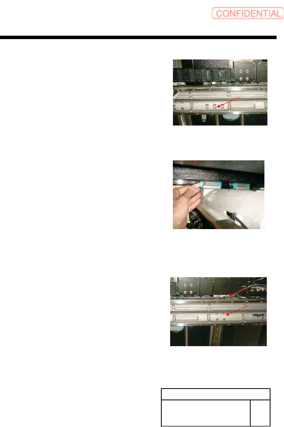
9, Fixed the screw in X-axis and nut holder of
a Y-axis ball screw, loosen it
POINT
Loosen it so that a ball screw does not have tension
10, Press to slide block and installation surface of the X-axis
Then tighten it (Left side LM-guide)
Confirm the gap between base level and LM-guide
POINT
Thickness gauge0.02mm do not enter
11, Slide block and installation surface of the X-axis tighten it
(Right side LM-guide)
POINT
Confirm Motion smoothly when move
Y-axis back and forth
XY axis movable parts
RPGB-11301-01
Change Procedure for
Y Axis
LM-GUIDE
SEET
6/9
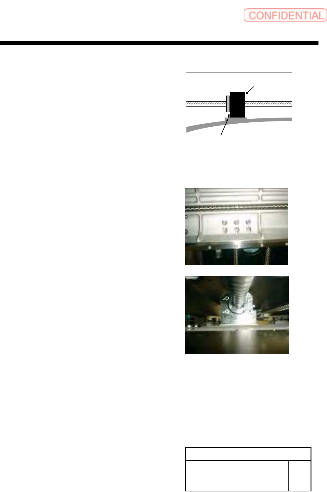
12, Confirm the position of X axis frame,
2 – 3mm from the motor side of mechanical end
Then Install ball screw of nut folder to the X-axis,
tighten it
12-1 Push a nut holder to a positioning pin
and tighten a screw at the opposite angle
12-2 Loosen a screw fixing a nut holder and the nut
of the ball screw and close it at the opposite angle again
12-3 again 12-1
12-4 again 12-2
POINT
Confirm Motion smoothly when move
Y-axis back and forth
Positioning Pin
Nut folder
XY axis movable parts
RPGB-11301-01
Change Procedure for
Y Axis
LM-GUIDE
SEET
7/9
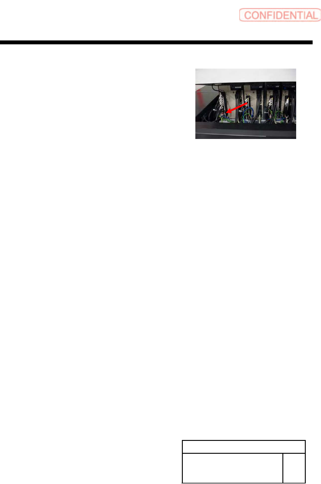
13 Connect the Y-axis motor power connector (YM)
14, Turn off/on power for the unit to return to home
15, Refer to the following
Auto Calibration HLGA-10320-02
16, Refer to the following
Pickup Position HLGA-10314-01
Pickup Position HLGA-10315-01