MAN00000772_SI-G200BB_SVCPDFA.pdf - 第712页
SI-G200/BB Service Manual Sony EMCS Corporation 30 Ibarajima Ooya-cho, Inazawa-shi, Aichi-PRE, 492-8545 JAPAN ©2014.2 by Sony EMCS Corporation 2nd Edition (12)
XY axis movable parts
RPGB-11301-01
Change Procedure for
Y Axis
LM-GUIDE
SEET
8/9
[Reference information]
Method to change a LM guide at the right and left at the same time
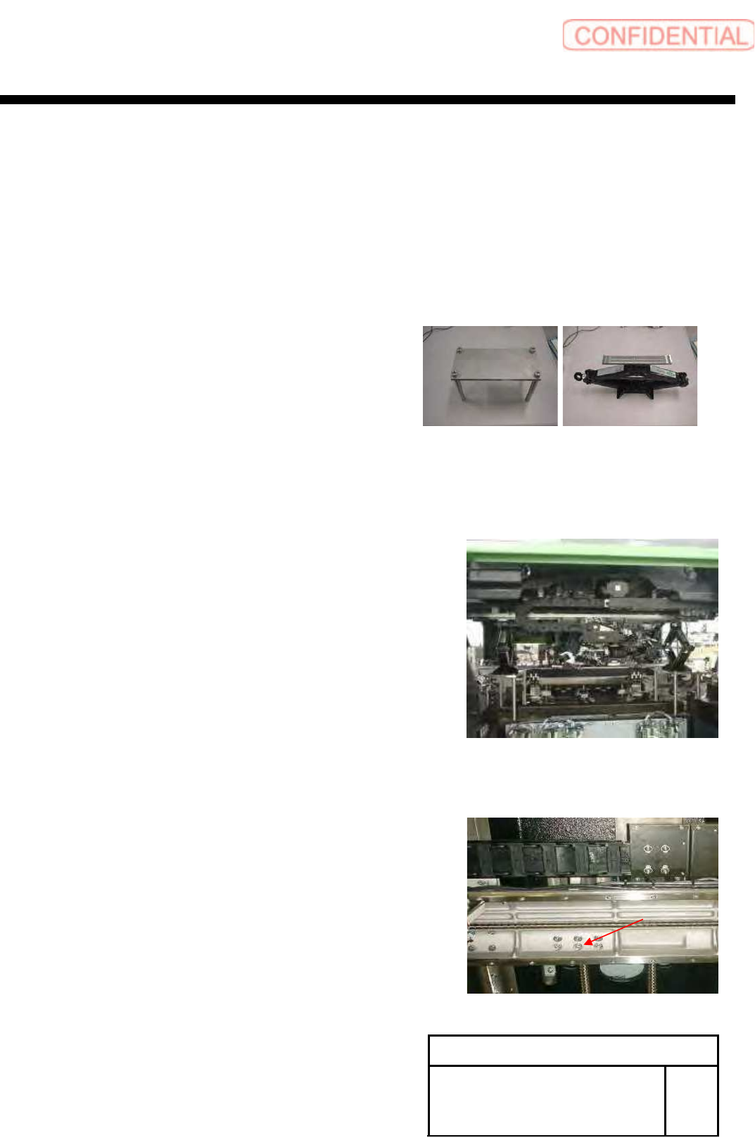
[Necessary jigs]
■ JIG stand
■ JIG jack
Working operation is same time as FRONT side and REAR side
1, Put the jig stand
Put the jig jack on jig stand for support of X-Axis
POINT
Please do not push up X-axis
JIG jack is fixed in the height in which a little motion remain
When there is not a JIG jack, substitute another JIG and use it
(Reference height of JIG stand to LM-guide rail 251mm)
2, Fixed the screw in X-axis and nut holder of
a Y-axis ball screw, unscrew it
XY axis movable parts
RPGB-11301-01
Change Procedure for
Y Axis
LM-GUIDE
SEET
9/9
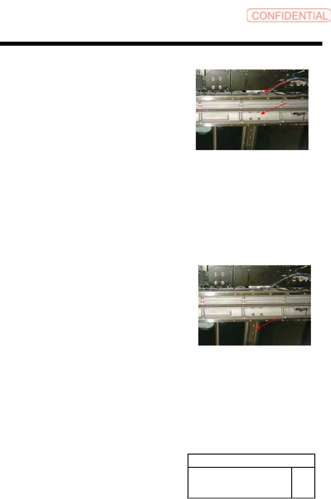
3, Fixed the screw in X-axis and slide block of
a LM-guide, unscrew it,
(slide block of front side and rear side)
POINT
Be careful not to drop a washer
4, lower the JIG jack to the position that is easy to operate.
POINT
Please keep the balance of the X-axis
Please attention on the interference around conveyor and Head
And do not stretch a wiring
5, Remove the LM-guide
(LM-guide of right and left)
6, method of the LM-guide install is the same
POINT
Take off a JIG jack after having installed an LM guide.
SI-G200/BB Service Manual
Sony EMCS Corporation
30 Ibarajima Ooya-cho, Inazawa-shi, Aichi-PRE, 492-8545 JAPAN
©2014.2 by Sony EMCS Corporation
2nd Edition (12)