MAN00000772_SI-G200BB_SVCPDFA.pdf - 第72页
Install Tray Unit (Including machine modification) SHEET 33/73 WKGB-10104-03 Installing Tray Unit (Including machine modification) [Inst allation of S axis unit] 1 Remove the discard box. NOTE: The unit of tray specifica…
Install Tray Unit (Including machine modification)
SHEET
32/73
WKGB-10104-03
Installing Tray Unit
(Including machine modification)
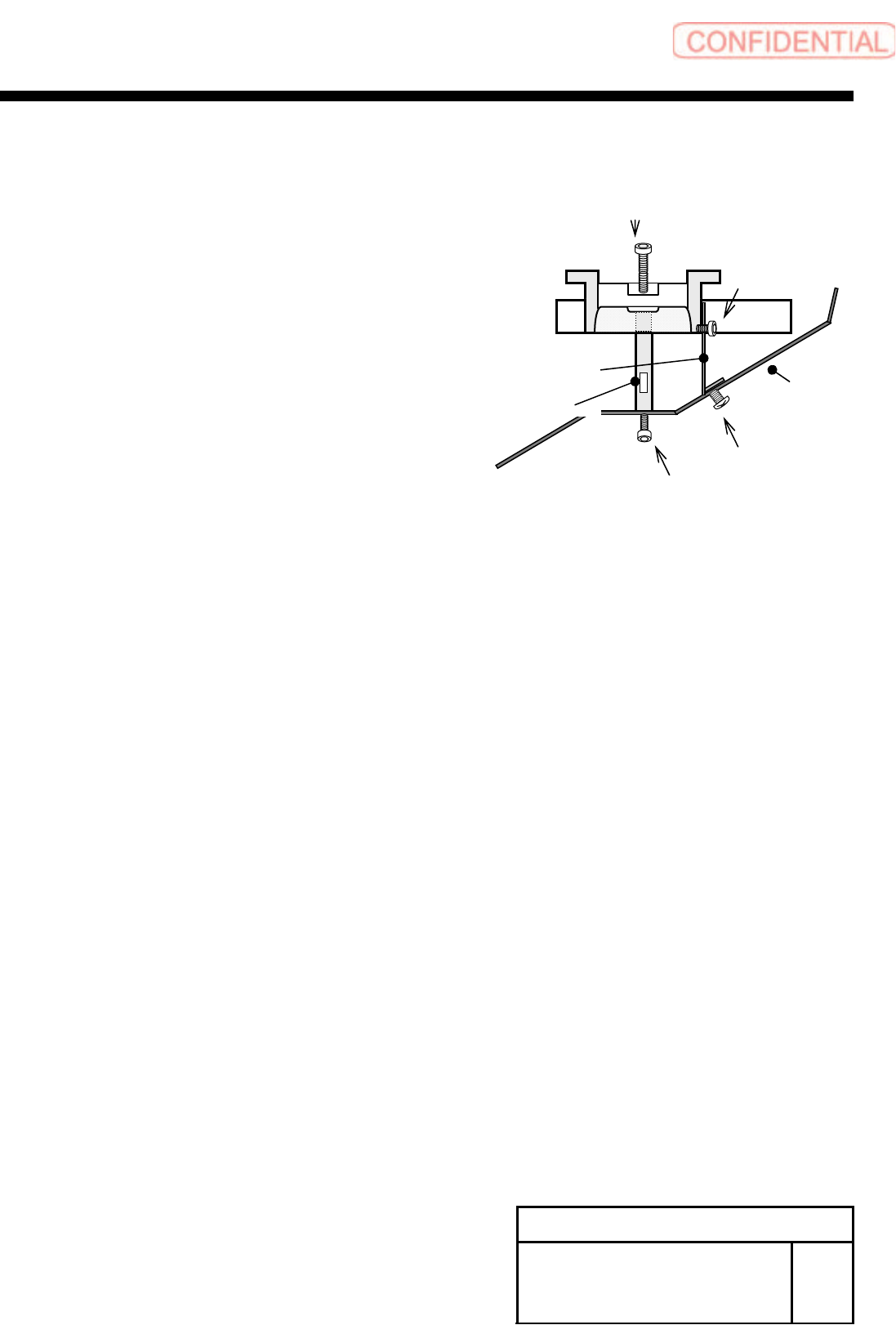
3 Install the shooter cover to the lower
side of the cassette table.
1. Fix the discharge guide bracket to the discharge
cover with the 3-T4x6.
2. Fix the discharge guide shaft to the discharge
cover with the 2-CP6x10.
3. Fix the Discharge guide shaft to the lower side of
the cassette table with the 2-cp6x30.
Discharge cover
Discharge guide bracket
Discharge guide shaft
3-T4x6
2-CP6X30
3-CP4x6
2-CP6X10
Install Tray Unit (Including machine modification)
SHEET
33/73
WKGB-10104-03
Installing Tray Unit
(Including machine modification)
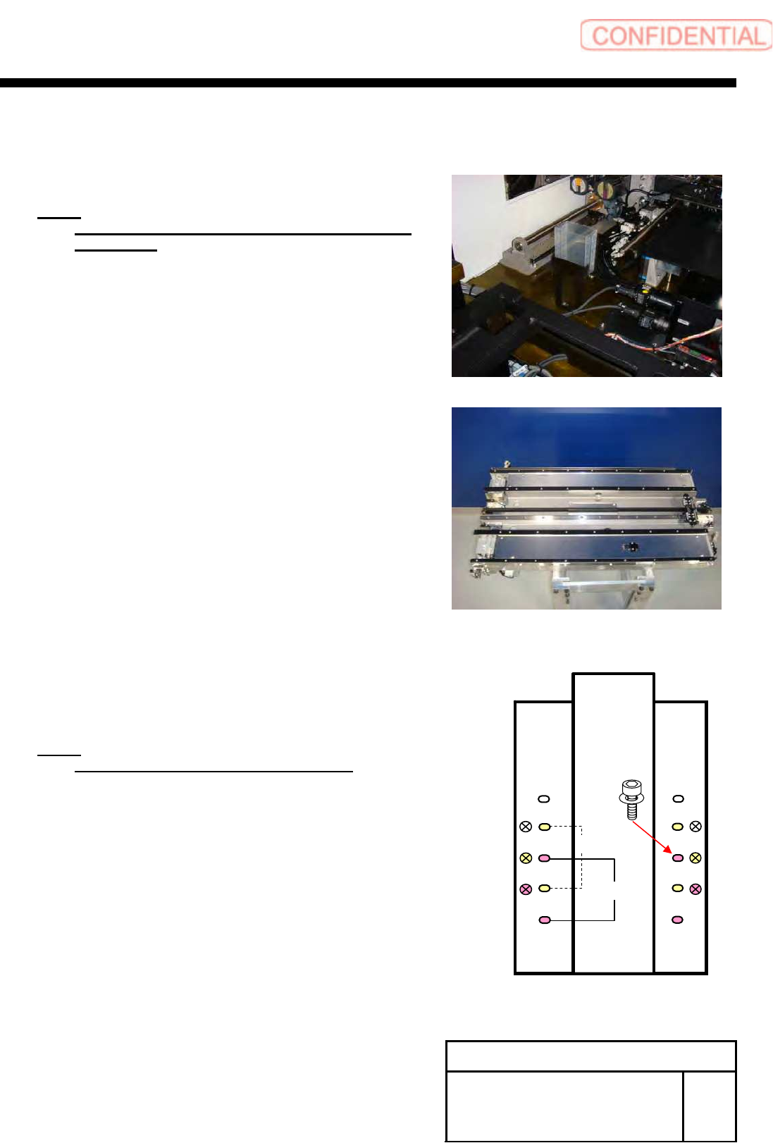
[Installation of S axis unit]
1 Remove the discard box.
NOTE:
The unit of tray specification essentially uses the
discard box.
2 Loosen the 8-+T4x8 on the upper
section of the S axis unit to remove the
cover.
3 Set to the position of the parallel pin on
the cassette table and place the S axis
unit on the cassette table.
NOTE:
Be careful not collide to the fixed camera.
4 Fix the S axis unit with the 4-CP6x20.
5 Install the cover using the 8-+T4x8.
410 ㎜
360 ㎜
Install Tray Unit (Including machine modification)
SHEET
34/73
WKGB-10104-03
Installing Tray Unit
(Including machine modification)
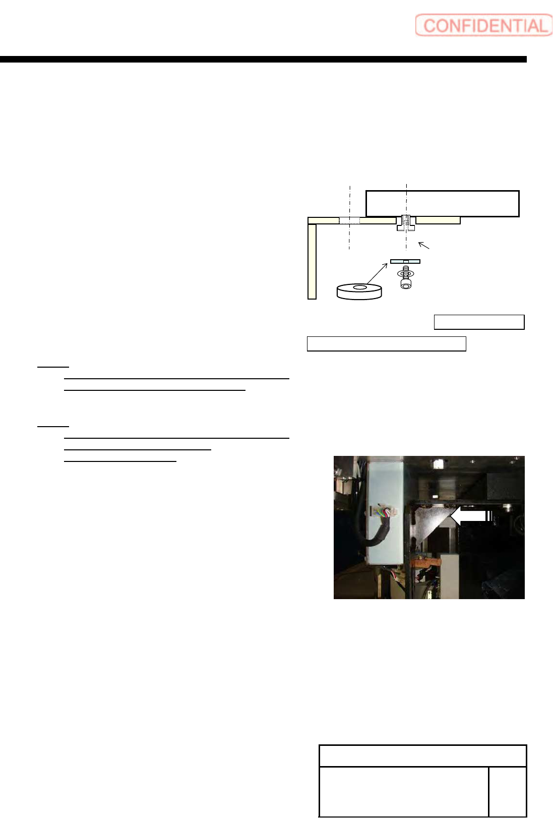
[Installation of mount bracket]
1 Install the mount bracket to the S axis
frame according to the conveyor width
specification.
NOTE:
Apply LOCKTITE 242 into the M10 thread
section on the spacer for mount base.
NOTE:
Fix temporarily at the position in which the
mount bracket was drawn out
outside of the machine.
360mm
410mm
Unit body side→
← Tray unit body side
Spacer
Spacer for mount base