MAN00000772_SI-G200BB_SVCPDFA.pdf - 第81页
Install Tray Unit (Including machine modification) SHEET 42/73 WKGB-10104-03 Installing Tray Unit (Including machine modification) 3. Adjust position of the projection side sensor head so that the conditions are satisfie…
Install Tray Unit (Including machine modification)
SHEET
41/73
WKGB-10104-03
Installing Tray Unit
(Including machine modification)
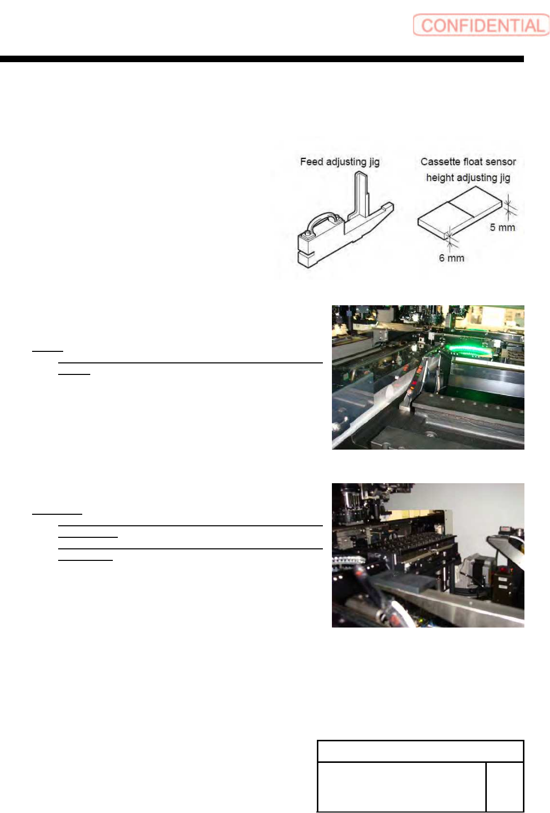
[Adjustment of cassette floating detection sensor]
[Necessary jig and Tools]
・Feed adjusting Jig
・Cassette float sensor height adjusting Jig
1 Set threshold of the sensor amplifier to 200.
NOTE:
Press the UP,DOW buttons and set the green indication
to 200.
2 Adjust position of the sensor so that the
following conditions are satisfied.
Condition:
When thickness is 5mm. Light receiving level should be
200 or more.
When thickness is 6mm. Light receiving level should be
200 or less.
1. Put the Feed adjusting Jig onto the Z101.
2. Put the Cassette float sensor height adjusting Jig
onto the Feed adjusting Jig.
Install Tray Unit (Including machine modification)
SHEET
42/73
WKGB-10104-03
Installing Tray Unit
(Including machine modification)
3. Adjust position of the projection side sensor head
so that the conditions are satisfied.
4. Put the Feed adjusting Jig and the Cassette float
sensor height adjusting Jig onto the Z117.
5. Adjust position of the light receiving side sensor
head so that the conditions are satisfied.
6. Put the Feed adjusting Jig and the Cassette float
sensor height adjusting onto the Z108.
7. Check position of the sensor so that the conditions
are satisfied.
NOTE:
When the condition of the light receiving level is not
satisfied, please adjustment sensor position again.
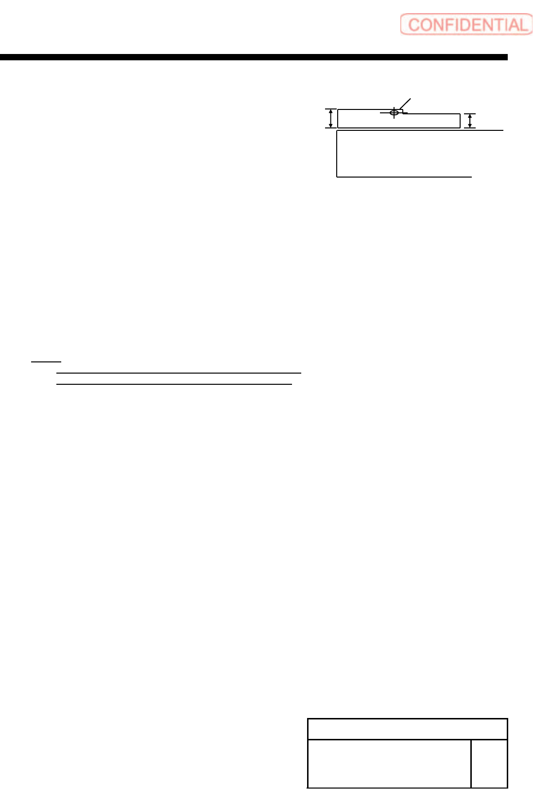
Feed adjusting Jig
6 ㎜
5 ㎜
Light axis position

Install Tray Unit (Including machine modification)
SHEET
43/73
WKGB-10104-03
Installing Tray Unit
(Including machine modification)
[Setup of software limit (+YR)]
1 Temporarily expand the software limit
only for the rear head.
1. Open
“c:¥asm¥mcdata2¥ac_param.ini” by
word pad and add 100 to
“SOFT_LIMIT_PLUS” for [AC_Y].
2. Overwrite and save
“c:¥asm¥mcdata2¥ac_param.ini.”
2 Power off and Re-boot machine.
3 Perform pickup position teaching for the
rear supply section.
NOTE:
For procedure of pickup position teaching, refer to
“Pickup position setup procedure [HLGB-10312-01].”
4 Move the rear head to the Z101 and
press the XY button for the M/C
SETUP/ORG OFFSET.
5 Assign the indicated Y axis position into
the following equation.
Equation:
Software limit(+YR)
= Y axis position of Z101(R) + 1.2
Example:
Software limit (+YR) = 40.476 + 1.2 = 41.676
6 Open “c:¥asm¥mcdata2¥ac_param.ini”
by word pad and change a value of
“SOFT_LIMIT_PLUS” for [AC_Y].
7 Overwrite and save
“c:¥asm¥mcdata2¥ac_param.ini”, and
re-boot machine.