MAN00000772_SI-G200BB_SVCPDFA.pdf - 第97页
Install Tray Unit (Including machine modification) SHEET 58/73 WKGB-10104-03 Installing Tray Unit (Including machine modification) 20. Select “01 ~ 05” from the dropdown list. 21. Press the SET #1 button to open the VU A…
Install Tray Unit (Including machine modification)
SHEET
57/73
WKGB-10104-03
Installing Tray Unit
(Including machine modification)
7. Close the shutter to return to the Tray Offset
screen.
8. Again, press the SET #1 button to open the VU
Axis screen.
9. Press the Set button on the VU Axis screen to
close.
10. Press the Set button on the Tray Offset screen.
11. Press the SET #2 button on the Tray Offset screen
to open the VU Axis screen.
12. Relative-move by 48[mm] from the supply No. 501.
13. Open the shutter on the cassette screen for
MANUAL.
14. Check that the tray pallet can smoothly move
between the tray rack and the S axis.
NOTE:
If transit of the tray pallet is not smooth,
adjust height of the tray pallet To a height
which allows smooth transit by JOG
operation.
15. Close the shutter to return to the Tray Offset
screen.
16. Again, press the SET #2 button on the Tray Offset
screen to open the VU Axis screen.
17. Press the Set button on the VU Axis screen to
close.
NOTE:
The
calculate button will be enable.
18. Press the Calculate button.
19. Press the Set button on the Tray Offset button.
Install Tray Unit (Including machine modification)
SHEET
58/73
WKGB-10104-03
Installing Tray Unit
(Including machine modification)
20. Select “01~05” from the dropdown list.
21. Press the SET #1 button to open the VU Axis
screen.
22. Relative-move by 12[mm] from the supply No. 505.
20. Perform setup from Z506 to Z515 by the same
procedure.
Reference (Moving amount on each stage):
Z501(1 ST SET)
~ Z505(2 ND SET) 48[mm]
Z505(1 ST SET)
~ Z506(2 ND SET) 12[mm]
Z506(1 ST SET)
~ Z510(2 ND SET) 48[mm]
Z510(1 ST SET)
~ Z511(2 ND SET) 12[mm]
Z511(1 ST SET)
~ Z515(2 ND SET) 48[mm]
4 After M/C org. Perform setup for supply
height of VL axis similarly to the VU axis.
Install Tray Unit (Including machine modification)
SHEET
59/73
WKGB-10104-03
Installing Tray Unit
(Including machine modification)
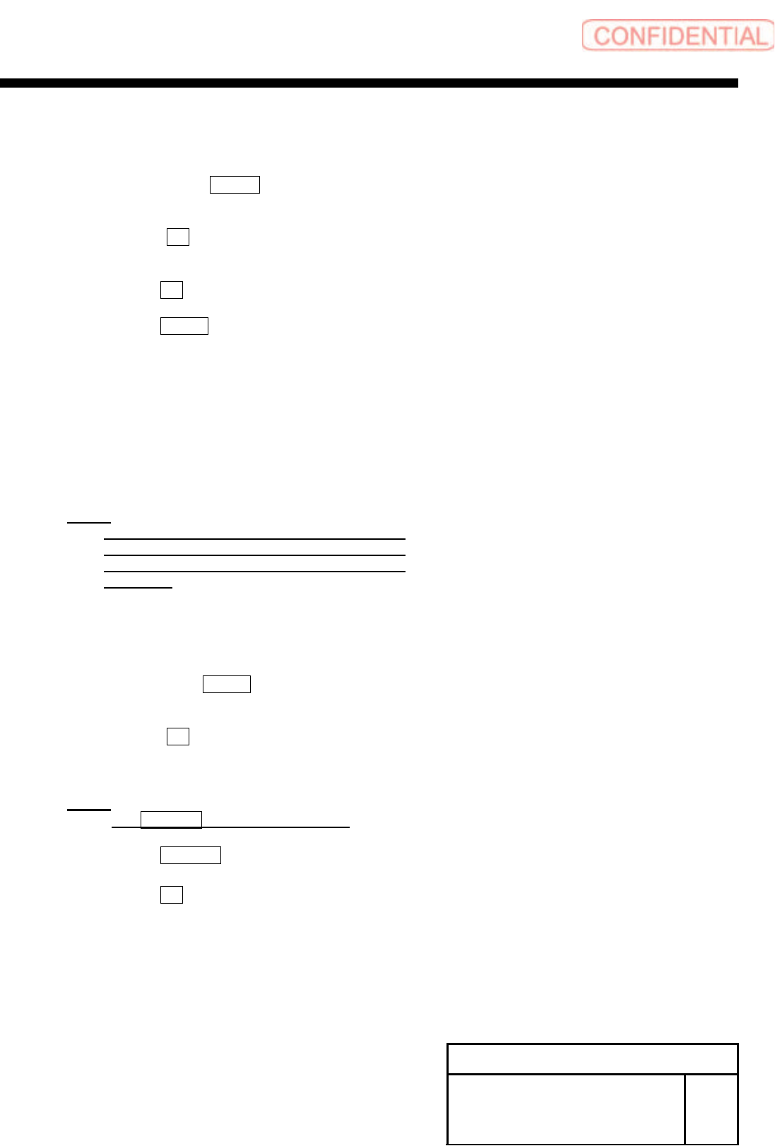
[V axis software limit setup]
1 Temporarily expand a value of the software limit.
1. Open “c:¥asm¥mcdata2¥ac_param.ini” by word pad.
2. Add an absolute value 100 to “SOFT_LIMIT_PLUS” and
”SOFT_LIMIT_MINUS” in [AC_VU] respectively.
3. Add an absolute value 100 to “SOFT_LIMIT_PLUS” and
“SOFT_LIMIT_MINUS” in [AC_VL] respectively.
4. Overwrite and save “c:¥asm¥mcdata2¥ac_param.ini”
and restart the unit.
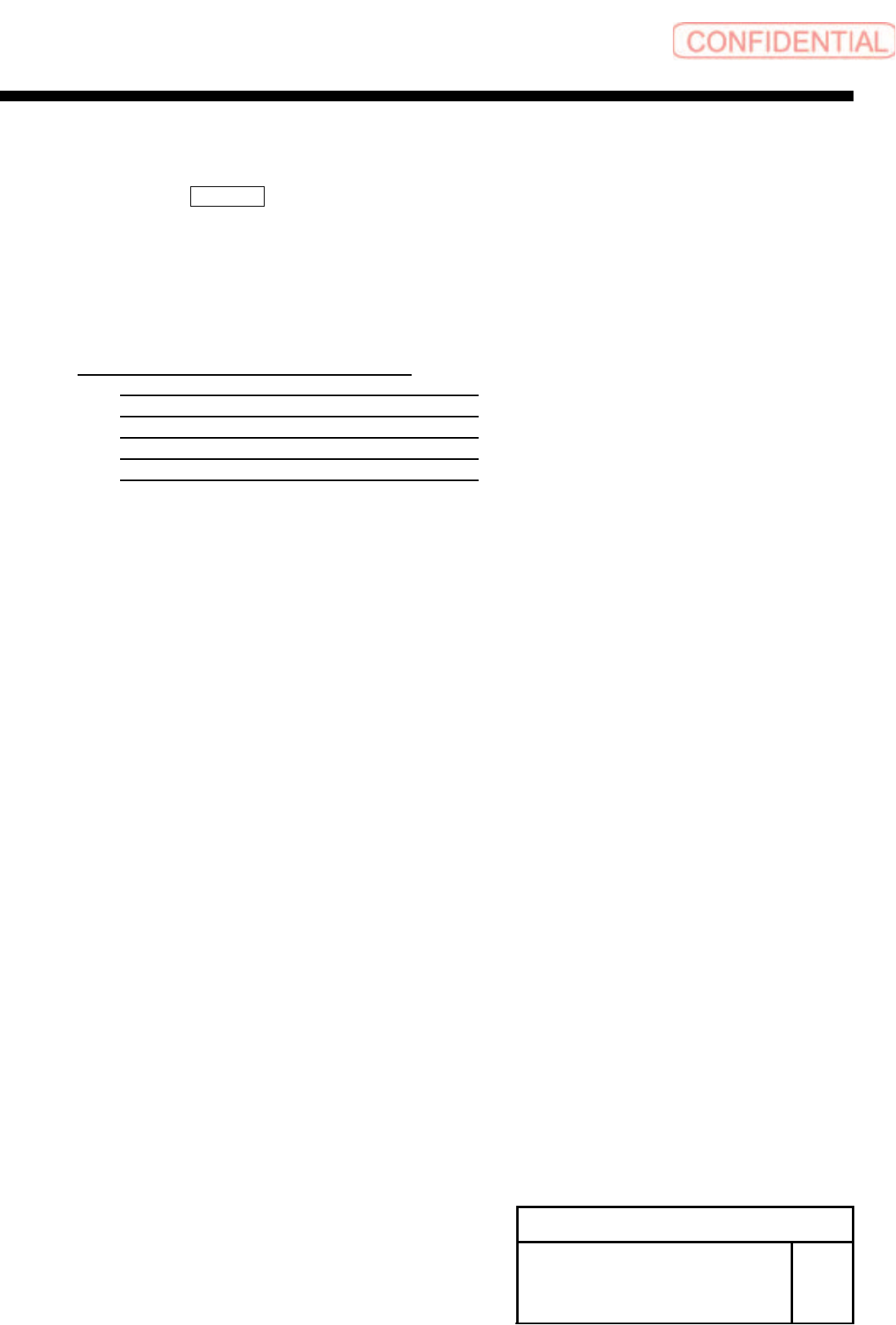
2 Remove the tray unit side cover of upper
and lower.
3 Return the unit to the origin.
4 Check position of the VU axis positive side
OT sensor.
1. Manually move the VU axis upward by JOG.
NOTE:
Move it by JOG every time while checking the
position.
2. Check the position of the UV axis immediately
before emergency stop.