00192801-01 - 第65页
User Manual V 1.15 - Productivity Lift 6 Set-up mode Software version V 40. 1 1 Edition 01/2001 6.4 Underneath buffer 57 $Y DLODELOLW\RI5DPSXS5DPSGRZQPRGHGHSHQGL QJRQPDFKLQHW\SH The ra mp up, r amp dow …
6 Set-up mode User Manual V 1.15 - Productivity Lift
6.3 Ramp up mode / Ramp down mode Software version V 40.11 Edition 01/2001
56
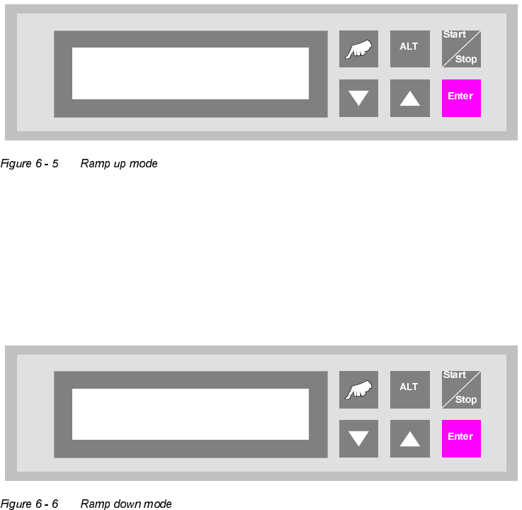
5DPSXSPRGH
PCB distribution parameter, which defines the loading sequence of the PCBs within a cluster of
Siplace units. The value of x depends on the number of Siplace units within a cluster.
The menu allows to set the value x between 0...9.
5DPSGRZQPRGH
PCB distribution parameter, which defines the unloading of the PCBs within a cluster of Siplace
units. The value of x depends on the number of Siplace units within a cluster.
The menu allows to set the value x between 0...9.
Ramp up mode
1 to x
Ramp down mode
1 to x
User Manual V 1.15 - Productivity Lift 6 Set-up mode
Software version V 40.11 Edition 01/2001 6.4 Underneath buffer
57
$YDLODELOLW\RI5DPSXS5DPSGRZQPRGHGHSHQGLQJRQPDFKLQHW\SH
The ramp up, ramp down mode depends on the selected machine type as defined in the table be-
low.
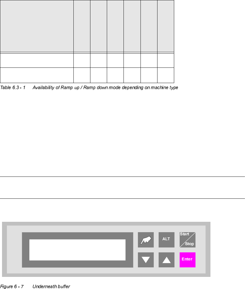
8QGHUQHDWKEXIIHU
The lower belts can be used as so-called underfloor buffers. This means that if the function is
switched on, two PCBs could be transferred on the belt. As a result, there is an additional further
storage space available for each belt.
127(
This menu is not displayed if the underfloor conveyor is switched off (see 5.8).
,QSXWPRGXOH
&OXVWHUPRGXOH
&URVVPRGXOH
&RQYHUW
&RQYHUW
2XWSXWPRGXOH
5DPSXSPRGH
;;;;
5DPSGRZQPRGH
;; ;;
Underneath buffer
Turned off
6 Set-up mode User Manual V 1.15 - Productivity Lift
6.5 PCB take over Software version V 40.11 Edition 01/2001
58
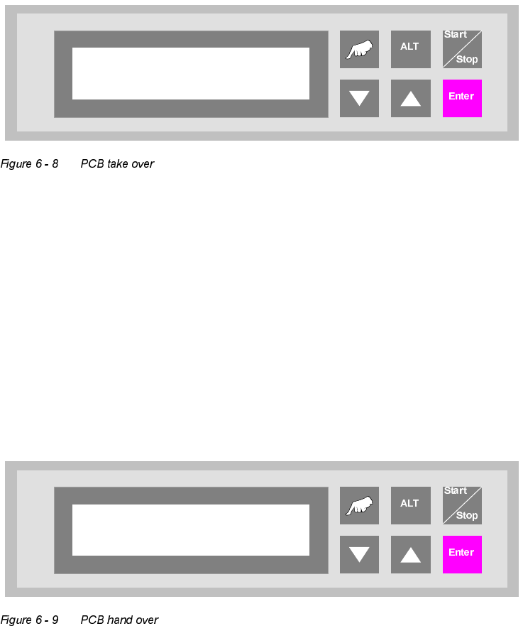
3&%WDNHRYHU
The possibility of defining the setting for PCB takeover at the inlet of the upper transport level. The
following settings are possible:
Double track : Depending on the request signals, PCBs are taken at the inlet alternately
from track 1 and track 2.
Track 1 : PCBs are taken from track 1 only
Track 2 : PCBs are taken from track 2 only.
3&%KDQGRYHU
The possibility of defining the setting for PCB hand over at the outlet of the upper transport level.
The following settings are possible:
Double track : Depending on the request signals, PCBs are taken at the inlet alternately
from track 1 and track 2.
Track 1 : PCBs are taken from track 1 only.
Track 2 : PCBs are taken from track 2 only.
PCB take over
Double track
PCB hand over
Double track