00192801-01 - 第84页
10 Description of interface Us er Manual V 1. 15 - Productivity Lift 10.2 SIEMENS interface definition Software version V 40. 1 1 Edition 01/2001 76
User Manual V 1.15 - Productivity Lift 10 Description of interface
Software version V 40.11 Edition 01/2001 10.2 SIEMENS interface definition
75
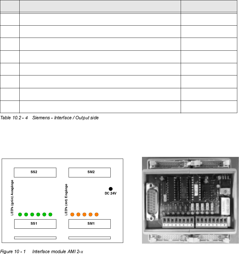
2XWSXWVLGH
,QWHUIDFHPRGXOH
3LQ 6LJQDO'HVLJQDWLRQ
28 24V from machine n+1
29 Interruption loop output to machine n+1
30 Earthing of the downstream machine
31 "Arrived" - signal input
32 "Ready" - signal input
35 "Handed over" - signal output for machine n+1
36 "Request" - signal output for machine n+1
37 Own earthing
S
S
1
A
n
g
e
k
o
m
m
e
n
S
S
1
A
n
g
e
k
o
m
m
e
n
S
S
1
B
e
r
e
i
t
S
S
2
A
b
g
e
g
e
b
e
n
S
S
2
A
n
f
o
r
d
e
r
u
n
g
S
S
1
S
t
ö
r
s
c
h
l
e
i
f
e
S
S
2
A
n
g
e
k
o
m
m
e
n
S
S
2
B
e
r
i
e
t
S
S
1
A
b
g
e
g
e
b
e
n
S
S
1
A
n
f
o
r
d
e
u
r
n
g
10 Description of interface User Manual V 1.15 - Productivity Lift
10.2 SIEMENS interface definition Software version V 40.11 Edition 01/2001
76

User Manual V 1.15 - Productivity Lift 11 Fault information
Software version V 40.11 Edition 01/2001
77
)DXOWLQIRUPDWLRQ
Malfunctions appear in the lower line of the display in the form of error messages. When the sys-
tem is initialised, the display also shows which function is being initialised. An initialisation is trig-
gered when the system is switched on and by the "F1" key.
0HVVDJHLQWKH
GLVSOD\
SRVVLEOHFDXVHDFWLRQ
&RYHURSHQ
A cover or door protected by an interlock switch is open
Close cover
(UUZLGWKLQOHW
The width at the inlet does not tally with the width of the previous unit.
Check the widths and restart the system if necessary.
:LGWKDGMXVWGHI
No final position is reached when adjusting the width or the referencing.
Check sensors.
,QWHUORFNEULGJHG
The key switch to bridge the safety switch is in the service setting. Automatic
operation is therefore not possible.
Return the safety switch to operation, remove the key and restart the system.
/LIWQRWXS
Top conveyor is not detected by the sensor in its upper position. Other functions
and processes can not be initiated.
Check the sensors and the drive function.
/LIWQRWGRZQ
The sensor in its lower position does not detect the shuttle. Other functions and
processes can not be initiated.
Check the sensors and the drive function.
/3EORFNHG«
A PCB is blocked in the system. The area containing the PCB is displayed by
the error message (see Figure 11 - 1 Fault information LP blocked):
LF1 = upper belt in the lift
LF2 = lower belt in the lift
TR1 = underfloor conveyor - take-over area
TR2 = underfloor conveyor - hand-over area
Remove the jammed PCB from the area and restart the system.
3&%DQQXDWHG
The maximum time (Menu chapter 5.5) for the conveyor is run up without the
transfer of the PCB to the following lift
In order to transfer the PCB and to restart the automatic running mode the
signal has to be confirmed by the user with the "Enter" cursor.
(PHUJHQF\VWRS
Emergency stopping switch pressed or 24V power supply defective.
Unlock emergency stopping switch (two per system) or check the 24V fuse.
5$0(UURU
System failure
Turn off the main switch, wait 1 minute and turn on again.
)DXOWEHOW
The underfloor conveyor isn’t in the right position installed.
Check the position.
)DXOWOLIW
Lift drive defective: Timeout, the Lift doesn’t arrive one of the defined positions
in this time.
Check the function of the drive and the motor controller.