A10011-ASM-T45-EN-Spec-E_DMS.pdf - 第14页
14 Placement Heads Nozzle Changer Nozzle changer for the SIPLACE CP14 Number of nozzle holders max. 80 Number of nozzle magazines 4 Nozzle types 4xxx Nozzle changeover time Approx. 2s per nozzle Compressed air connection…
13
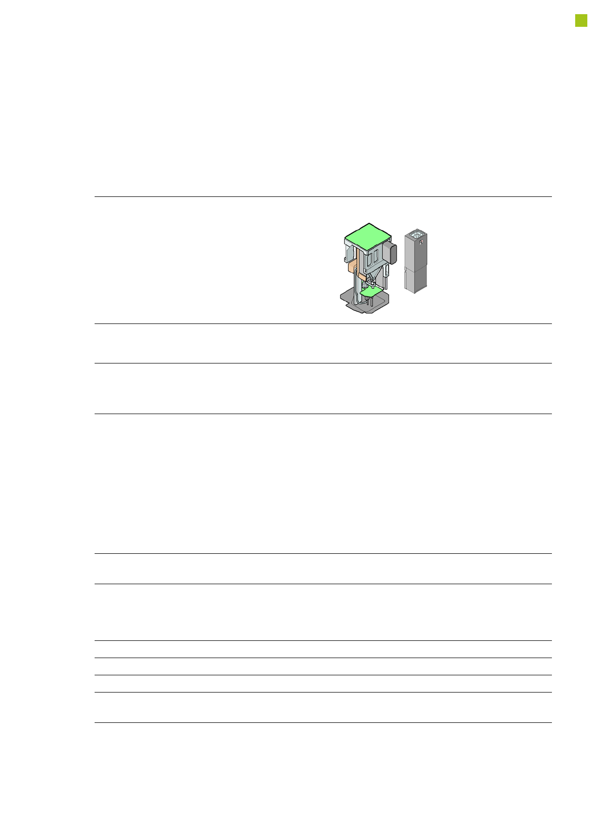
Placement Heads
SIPLACE PP
SIPLACE PP
with stationary
camera type 36 GigE
(Standard)
with stationary
camera type 33 GigE
(Fine pitch)
with stationary
camera type 25 GigE
(Flip chip)
Range of components
a
a) Please note that the range of components that can be placed is also affected by the pad geometry, customer-specific
standards, component packaging tolerances and component tolerances.
0603 to SO, PLCC,
QFP, BGA, special
components, bare dies,
flip-chips
0402 to SO, PLCC,
QFP, BGA, special
components, bare dies,
flip-chips
0201 to SO, PLCC, QFP,
sockets, plugs, BGA, special
components, bare dies, flip-
chips, shields
Component specification
Max. height
b
Min. lead pitch
Min. lead width
Min. ball pitch
Min. ball diameter
Min. dimensions
Max. dimensions
Max. weight
c
b) 19 mm if one nozzle of the CP12/CP6 is removed. 8.5 mm if no nozzle of the CP12/CP6 is removed.
c) If standard nozzles are used
19 mm
0.4 mm
0.24 mm
0.56 mm
0.32 mm
1.6 mm x 0.8 mm
32 mm x 32 mm
(single measurement)
45 mm x 98 mm
100 g
19 mm
0.3 mm
0.15 mm
0.35 mm
0.2 mm
1.0 mm x 0.5 mm
55 mm x 45 mm
(single measurement)
45 mm x 98 mm
100 g
19 mm
0.25 mm
0.1 mm
0.14 mm
0.08 mm
0.6 mm x 0.3 mm
16 mm x 16 mm
(single measurement)
100 g
Programmable set-down
force 1.0 N - 15 N 1.0 N - 15 N 1.0 N - 15 N
Nozzle types 5xx (standard)
4xx + adapter
8xx + adapter
9xx + adapter
5xx (standard)
4xx + adapter
8xx + adapter
9xx + adapter
5xx (standard)
4xx + adapter
8xx + adapter
9xx + adapter
X/Y accuracy
d
d) The accuracy value was measured using the vendor-neutral IPC standard
± 50 µm/3σ ± 50 µm/3σ ± 37.5 µm/3σ
Angular accuracy ± 0.053°/3σ ± 0.053°/3σ ± 0.053°/3σ
Illumination levels 6 6 6
Possible illumination level
settings
256
6
256
6
256
6

14
Placement Heads
Nozzle Changer
Nozzle changer for the SIPLACE CP14
Number of nozzle holders max. 80
Number of nozzle magazines 4
Nozzle types 4xxx
Nozzle changeover time Approx. 2s per nozzle
Compressed air connection 0.45 MPa (4.5 bar)
Nozzle changer for the SIPLACE CP12
Number of nozzle holders max. 48
Number of nozzle magazines 4
Nozzle types 30xx
Nozzle changeover time Approx. 2s per nozzle
Compressed air connection 0.45 MPa (4.5 bar)
Nozzle changer for the SIPLACE CP6
Number of nozzle holders
38xx
39xx
max. 24
max. 48
Number of nozzle magazines 4
Nozzle types 38xx/39xx
Nozzle changeover time Approx. 2s per nozzle
Compressed air connection 0.45 MPa (4.5 bar)
Nozzle changer for the SIPLACE TH/PP
Number of nozzle holders max. 16 for standard nozzles
4 for special nozzles or grippers
Nozzle types 5xx, standard
4xx with adapter
8xx with adapter
9xx with adapter
Nozzle changeover time Approx. 2 s per nozzle
15
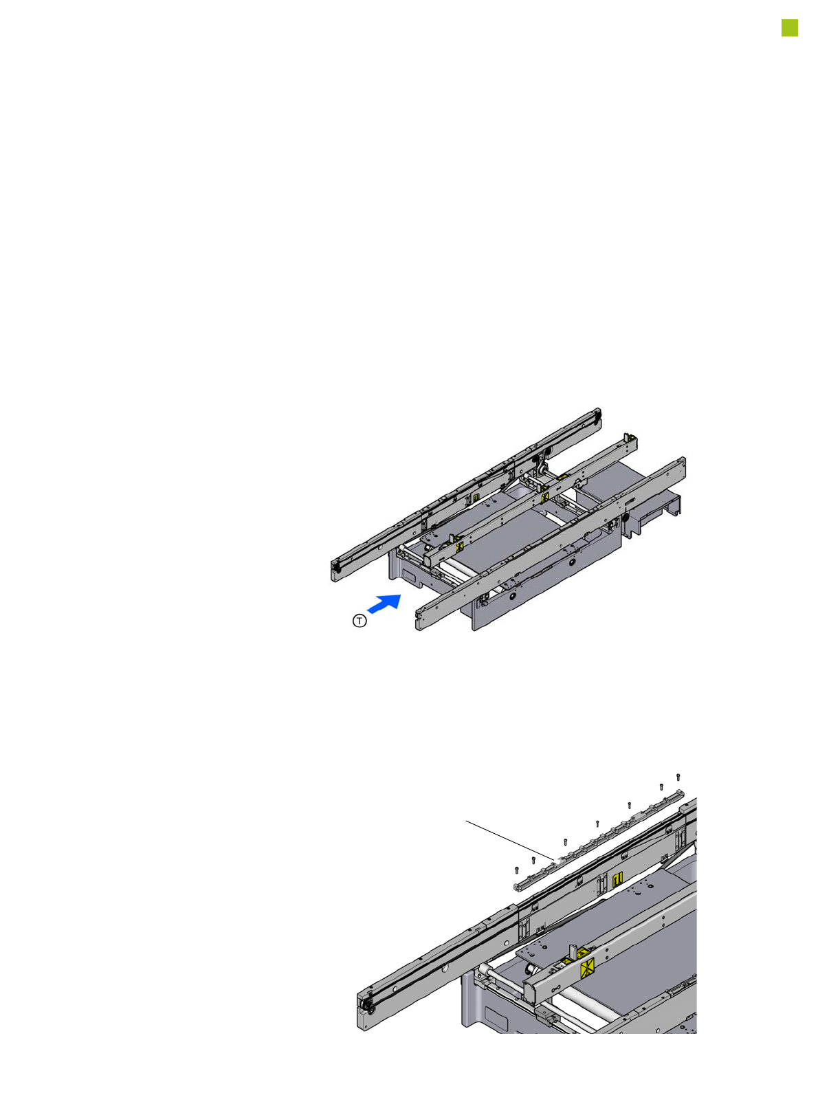
Board Conveyor
Boards are moved behind
one another, along a con-
veyor lane and into the
placement machine, where
they are placed. This con-
veyor variant is particularly
suitable for very wide boards.
Conveyor transport principle
When the board reaches the
placement area, it is gently
slowed down (braked). As
soon as the board has
reached its target position,
the conveyor belt is stopped
and the board is clamped
from below. The placement
process begins immediately
afterwards. The transporta-
tion and clamping of the
boards is monitored.
Adjustable conveyor clamp-
ing
The Adjustable conveyor
clamping is designed to cater
for standard E conveyor up
to 460 x 460 to handle PCB
with fiducials near the edge.
Top clamping are adjustable
so customer can fix any-
where to avoid PCB fiducials.
Position of conveyor sides
The conveyor can be easily
adjusted with the automatic
electrical width adjustment
system, to accommodate
various different board
widths.
Single conveyor
Adjustable conveyor
clamping