A10011-ASM-T45-EN-Spec-E_DMS.pdf - 第18页
18 PCB Warpage PCB warpage du ring placement PCB warpage downwards max. 0.5 mm Use the magnetic pin supports, to ach ieve this value. When there is warpage under 2 mm, the inkspots in the center of the board are also wit…
17
PCB Warpage
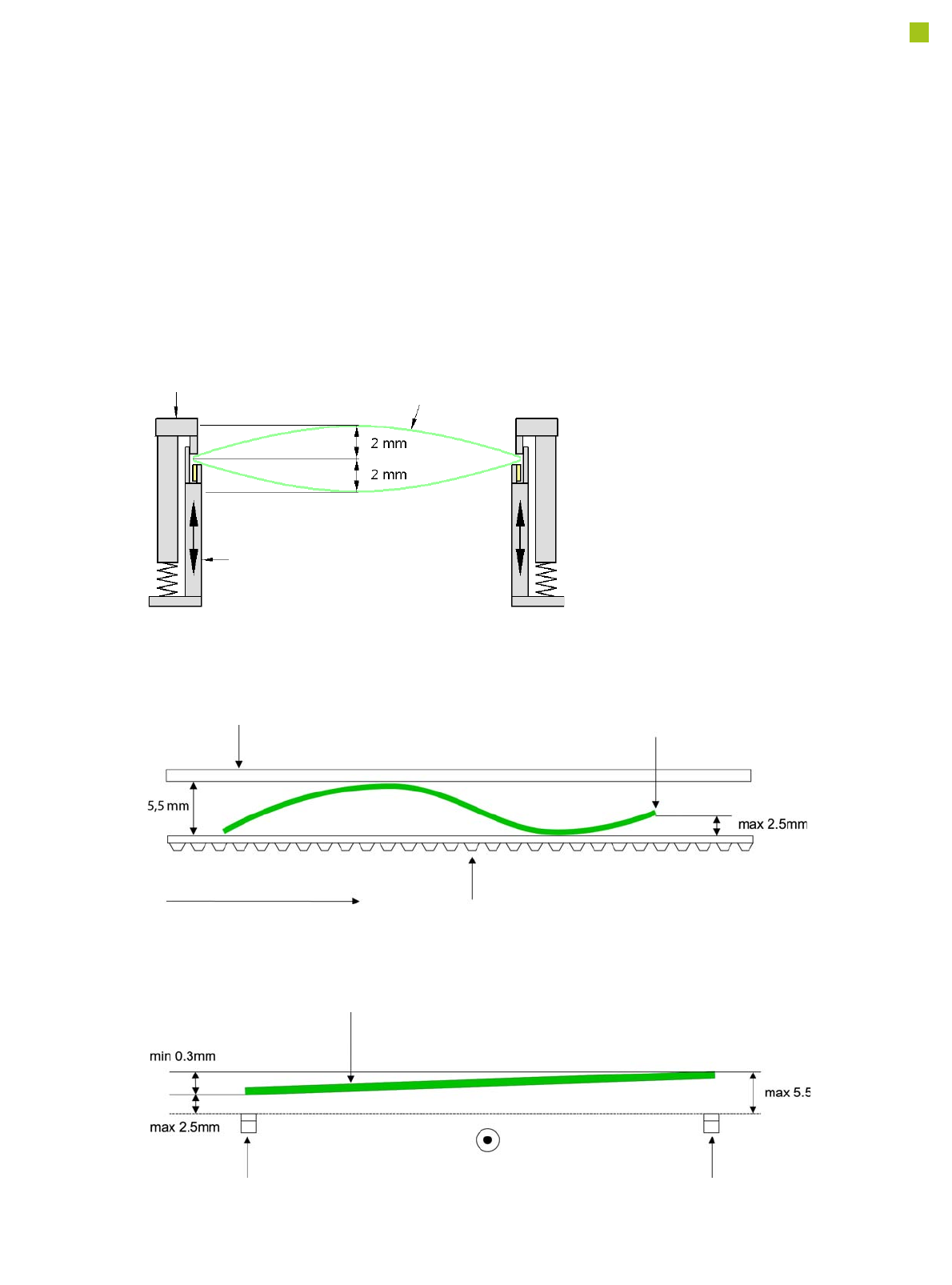
PCB warpage across the direction of travel
max. 1 % of the PCB diagonal, but not
exceeding 2 mm
PCB warpage on the conveyor
Fixed clamped edge
Movable clamping device
PCB
Fixed clamped edge
Conveyor belt
PCB transport direction
Front board edge
Front board edge
PCB warpage in direction of travel + PCB thickness < 5.5 mm
Bending up of front board edge max. 2.5 mm
Left conveyor belt
Right conveyor belt
PCB transport direction
18
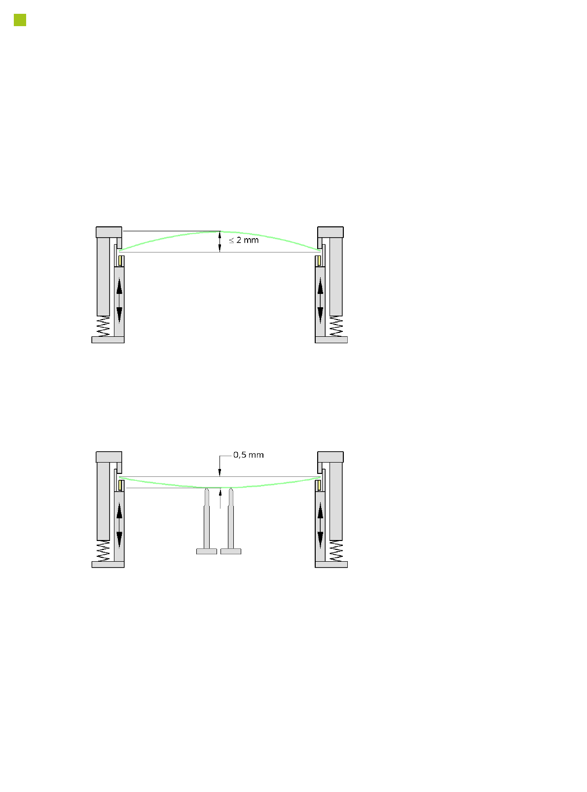
PCB Warpage
PCB warpage during placement
PCB warpage downwards max. 0.5 mm
Use the magnetic pin supports, to achieve
this value.
When there is warpage under 2 mm, the
inkspots in the center of the board are also
within the focus of the digital camera. When
all the tolerances are taken into account,
this value is reduced to 1.5 mm.
You should also note that the warpage
reduces the component height.
Magnetic pin support
19
Component Feeding
Component Trolley
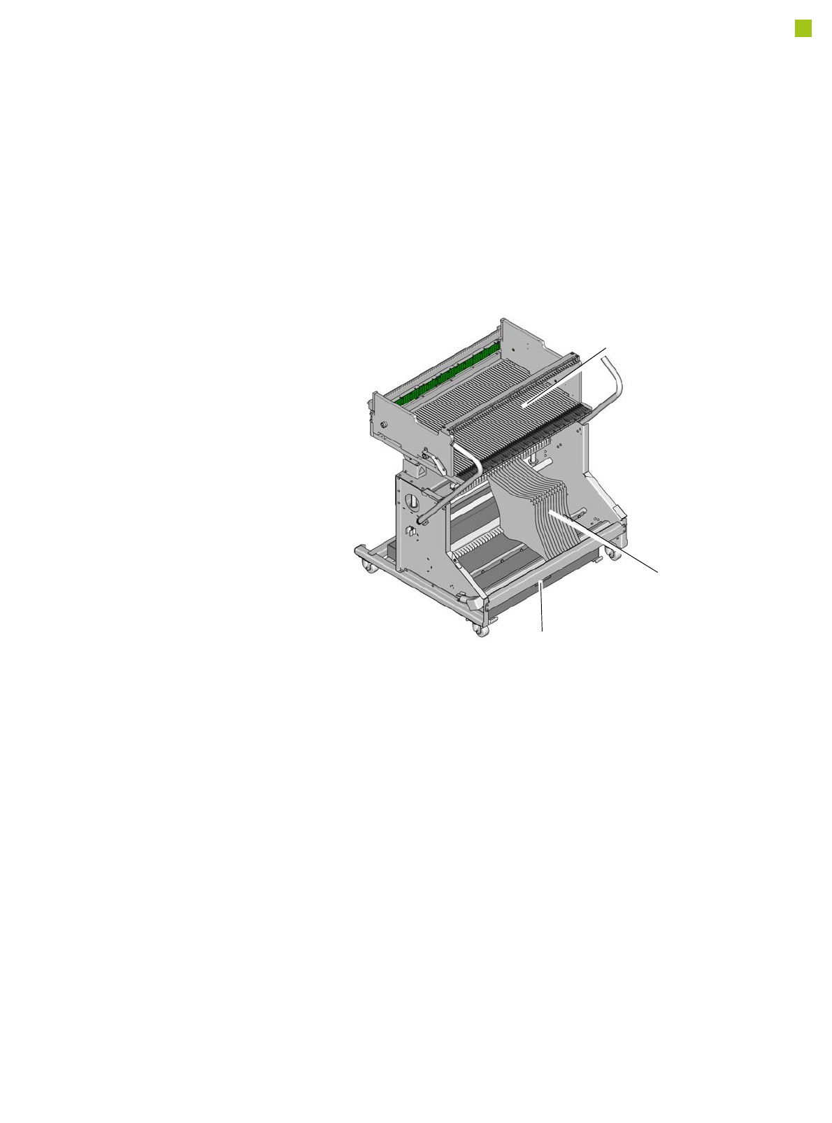
Component trolley
E by SIPLACE
The E by SIPLACE compo-
nent trolleys are independent
and easily maneuverable
modules. The E by SIPLACE
machines can accommodate
up to two component trolleys,
each with 60 tracks. The tape
reels are taken up into the
tape container of the compo-
nent trolley. A cutting device
on the machine automatically
cuts the used tape material.
The component trolleys can
be set up directly on the
machine or at an external
setup area with feeder mod-
ules. The benefits of offline
setup are that the configura-
tions can be prepared with-
out stopping the line. This
allows the setup to be
changed very quickly using
the changeover table princi-
ple. The E by SIPLACE com-
ponent trolleys also support
fast setting up and tearing
down of feeder modules
even during the placement
process.
The component feeders are
at rest during the placement
process - allowing tapes to
be spliced without stopping
the machine.
For safety reasons, unoccu-
pied locations are fitted with
so-called dummy feeder
modules.
Component trolley E by SIPLACE
Tape container
Waste container for remaining empty tape
Changeover table