A10011-ASM-T45-EN-Spec-E_DMS.pdf - 第27页
27 Digital SIPLACE Vision System The digital Vision system ensures fast and reliable component recognitio n, cou - pled with user-friend ly han - dling. The s ystem identifies each individual compon ent by its geometry a…
26
Component Feeding
Alternative Feeder Modules
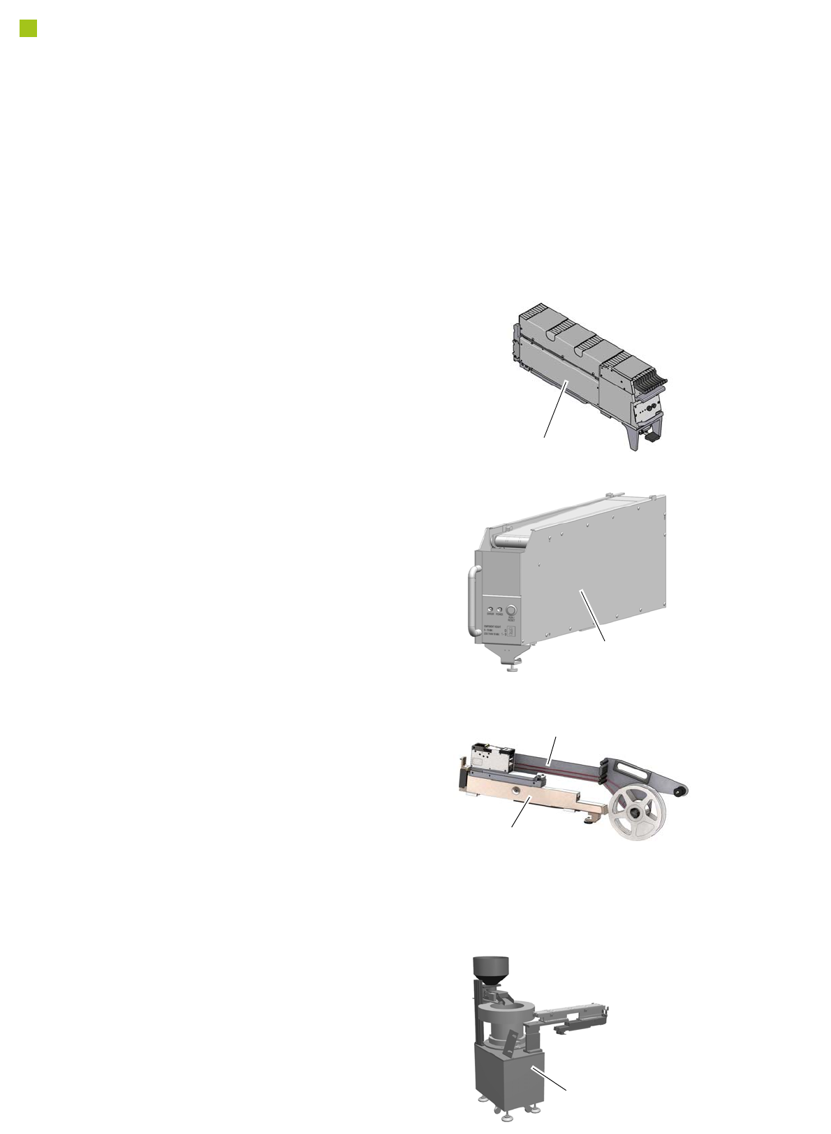
SIPLACE StickFeeder E
SIPLACE StickFeeder E
The SIPLACE StickFeeder E for E by SIPLACE
can be used on any E by SIPLACE feeder table
and can setup any number of stick / tube, with a
combined stick width up to 100 mm. The Stick-
Feeder for E by SIPLACE will occupy 10 tracks
on the feeder table and allows handling of sticks
up to a thickness of 23 mm (standard). Please
contact your dedicated E by SIPLACE distribu-
tor for stick thickness higher than 23 mm.
Feeder Adaptor RO E
Label Feeder
Label Feeder (OEM Product)
Via a dedicated Feeder Adaptor RO E, the
Label Feeders ALF12 and ALF14 can be setup
and used on E by SIPLACE. For further techni-
cal details please visit
http://label-feeder.com
and contact your dedicated E by SIPLACE dis-
tributor.
Feeder Adaptor RO E
The Feeder Adaptor RO E provides the neces-
sary interface to third party feeder, such as the
Label Feeder and Bowl Feeder. For further tech-
nical details please contact your dedicated E by
SIPLACE distributor.
SIPLACE Component
Reject Conveyor E
SIPLACE Component Reject Conveyor E
The SIPLACE Component Reject Conveyor E
is designed so that defective components (veri-
fied by placement machine vision system) are
placed onto conveyor belt and transferred out of
machine for operator retrieval. It is handled like
any other feeder for E by SIPLACE and can be
mounted onto its feeder tables.
Bowl Feeder (OEM Product)
Via a single or multiple Feeder Adapter E, the
Bowl Feeders can be setup and used on E by
SIPLACE. For further technical details please
contact your dedicated E by SIPLACE distribu-
tor.
Bowl Feeder

27
Digital SIPLACE Vision System
The digital Vision system
ensures fast and reliable
component recognition, cou-
pled with user-friendly han-
dling. The system identifies
each individual component
by its geometry and color.
Even complex component
shapes, such as flip chip or
CCGA are detected with high
reliability.
This component recognition
check is performed in a sin-
gle step, with no extra time
involved but with optimum
scanning of each individual
component.
This digital Vision system is
not only used in the compo-
nent cameras but also in the
PCB camera. In addition to
the precise recognition of
components, this also guar-
antees reliable detection of
inkspots and PCB fiducials.
The benefits at a glance:
• Extremely fast and reliable
component recognition
• Shortest cycle times
• Robust measurement
based on the geometry
and color
• Straightforward program-
ming
• Offline programming of
component shapes
• Rapid introduction of new
products (NPI)
• Open architecture allows
you to quickly adapt to
new requirements
• Optimum placement
results based on individ-
ual measurement of each
component
The SIPLACE Vision sys-
tem offers inspection rou-
tines and functions to
enhance the quality of com-
ponent recognition.
The benefits at a glance:
• Maximum placement
quality
• High first pass yield
• Reduction of operating
costs
Digital vision cameras
Component camera, type 23 GigE
Component camera, type 25 GigE
Component camera, type 30 GigE
Component camera, type 33 GigE
Component camera, type 36 GigE
Examples of digital vision system analysis times
Evaluation times only play a role in the P&P process.
01005 9 ms
PLC44 17 ms
BGA 225 balls 18 ms
28
Digital SIPLACE Vision System
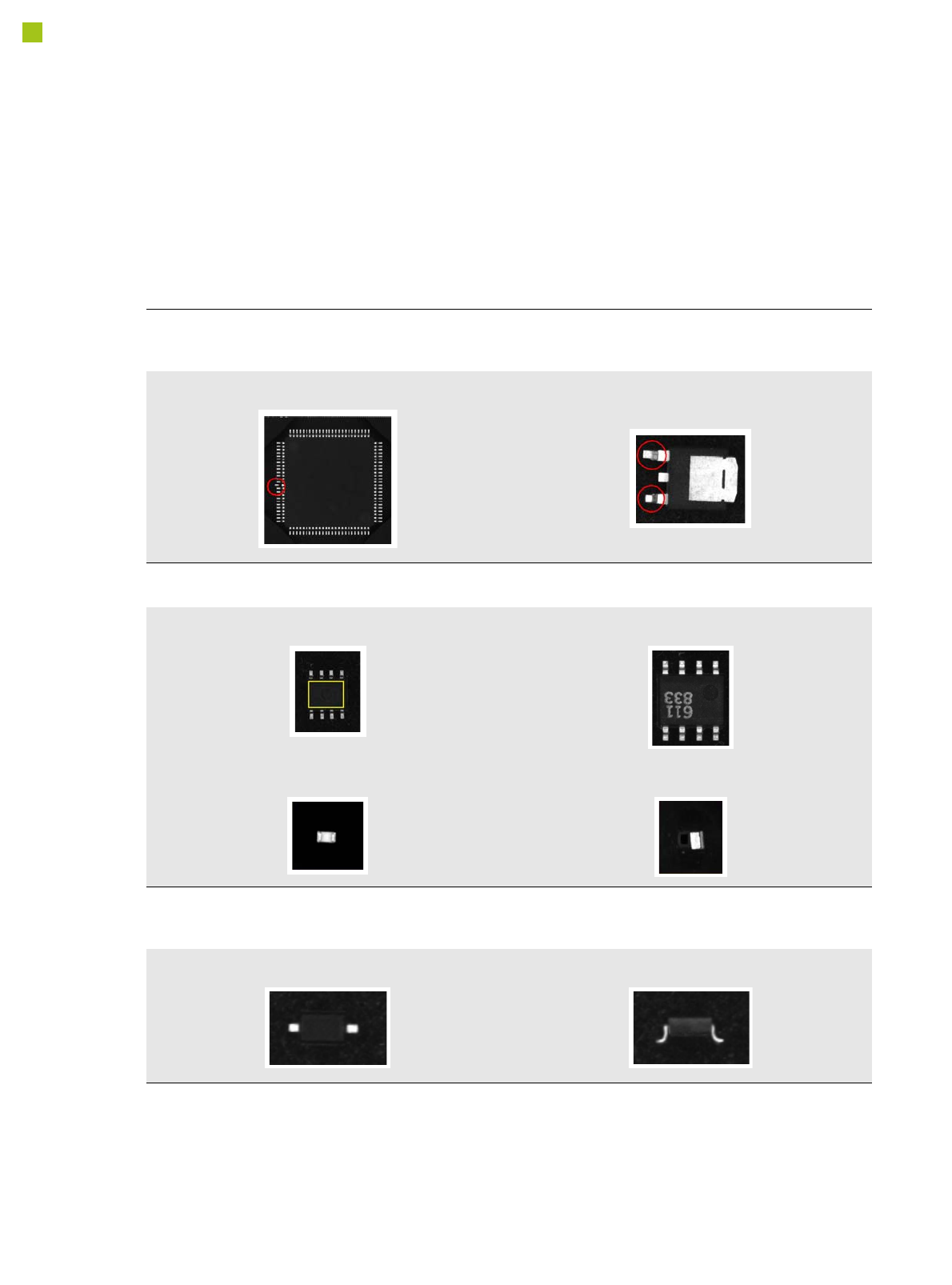
Checking the Component Quality
Overview of Key Functions
Recognizing the collinearity of components
Damaged or bent leads are recognized. This helps avoid solder-free connections during the subsequent solder-
ing process.
Damaged leads Damaged leads
Recognizing flipped (face down) or upright components
Both chip and IC component shapes (e.g. SOT) recognized in flipped (turned face down) or upright state.
SOT OK SOT “face down”
Flipped chip Chip upright
Checking the lead width
The optical checking of the lead width recognizes tilted or damaged leads. This helps to recognize e.g. diodes
with tilted leads.
Lead width OK Tilted lead