A10011-ASM-T45-EN-Spec-E_DMS.pdf - 第34页
34 01005 Placement In its stand ard version, the E by SIPLACE is designed for placement of 01005 compo - nents (0.4 mm x 0.2 mm) . The SIPLACE component library already contains the contours and dimensio ns of 01005 comp…

33
Vision Sensor Technology
Reading the barcode and data matrix code with a
PCB camera
1D Barcodes
Code types Code 39
Code 93
Code 128
EAN-8 (AddOn 2, AddOn 5), EAN-13 (AddOn 2, AddOn 5)
Interleaved 2 of 5 (station software version 709.1 or higher required)
Minimum width of bar 50 µ
If the quality of the marking is high enough, the width can be reduced
down to 30 µ.
Maximum size of barcode X
≤ 30 mm and Y ≤ 30 mm, or
X ≤ 10 mm and Y ≤ 100 mm, or
X
≤ 100 mm and Y ≤ 10 mm
Minimum height of symbol 5% of length of whole symbol.
Symbol angle All symbol angles will be accepted.
Inverse symbols Light bars on a dark background will be accepted.
(Station software version 708.0 or higher required)
Mirrored symbols Mirrored symbols will be accepted.
(this corresponds to a rotation of 180 degrees for 1D codes)
Region of Interest (ROI) The area on the board, in which the barcode is searched for (ROI),
should not exceed the following values:
ROI (direction of reading)
≤ 3 * symbol width
ROI (vertical to direction of reading) ≤ 10 * symbol width
Uniformity of bars and spaces Each bar and space represents 1 to 4 bits (applies to all code types
implemented), whereby the number of bits corresponds to the width of
the bar/space. When the barcode is read with the PCB camera, it is
assumed that the code is flat. This is why the same nominal width is
applied to all bars and spaces in the symbol when reading 1D bar-
codes with the PCB camera. As a consequence, barcodes cannot be
read if a bar/space with n bits appears to be smaller than another bar/
space with n-1 bits.

34
01005 Placement
In its standard version, the E
by SIPLACE is designed for
placement of 01005 compo-
nents (0.4 mm x 0.2 mm).
The SIPLACE component
library already contains the
contours and dimensions of
01005 components. Spe-
cially developed component
nozzles of type 1005 are also
available for the E by
SIPLACE. These are
adjusted to the shape and
size of the 01005 compo-
nents and have - as with all
other SIPLACE nozzles - a
highly wear-proof ceramic tip
and flexible nozzle seat. This
guarantees maximum preci-
sion and process reliability.
Optimized pickup is guaran-
teed by the ideal feeding
conditions in the SIPLACE
SmartFeeder E module. The
smaller the elements to be
picked up, the more accurate
the pickup needs to be.
Pickup is performed contact-
free to compensate minor
inaccuracies e.g. from com-
ponent or pocket tolerances
and to prevent mechanical
damage to the components.
The design of the SIPLACE
SmartFeeder E modules
takes this problem into
account: new motors and the
reduced use of fine mechan-
ics help. Small components
can be placed without perfor-
mance loss with minimum
pitch and irrespective of the
larger components which are
next to the 01005 compo-
nent. This equates to true
01005 capability. As a rule
with 01005 placement, a
finely tuned overall process
is the basic requirement if
you want to achieve excel-
lent results.
For high volume production
It's recommended that CP14
be use for 01005 placement.
The CP14 head is immediate
ready for 01005 placement.
For CP12 head
An additional option - 01005
package CP12 E (sales num-
ber: 288605), needs to be
purchase. This option
includes nozzles and three
low force sleeves needed for
01005 placement by CP12
head.
The following table shows typical values for 01005 placement,
which can be achieved with a E by SIPLACE, provided the rel-
evant underlying conditions are fulfilled:
Machine type
E by SIPLACE
Placement head SIPLACE CP14 with
component camera type 23 GigE
Feeder module type SIPLACE SmartFeeder 8 mm E
or
SIPLACE SmartFeeder 2x8 mm E
Pickup rate ≥ 99,97%
Dpm rate ≤ 5
Pad width ≥ 200 µm
Pitch ≥ 100 µm
Components (L x W x H) 400 µm x 200 µm x 200 µm (±20 µm)
Number of pixels for a
01005 component
275
Solder paste type 5
Template thickness 60 µm
35
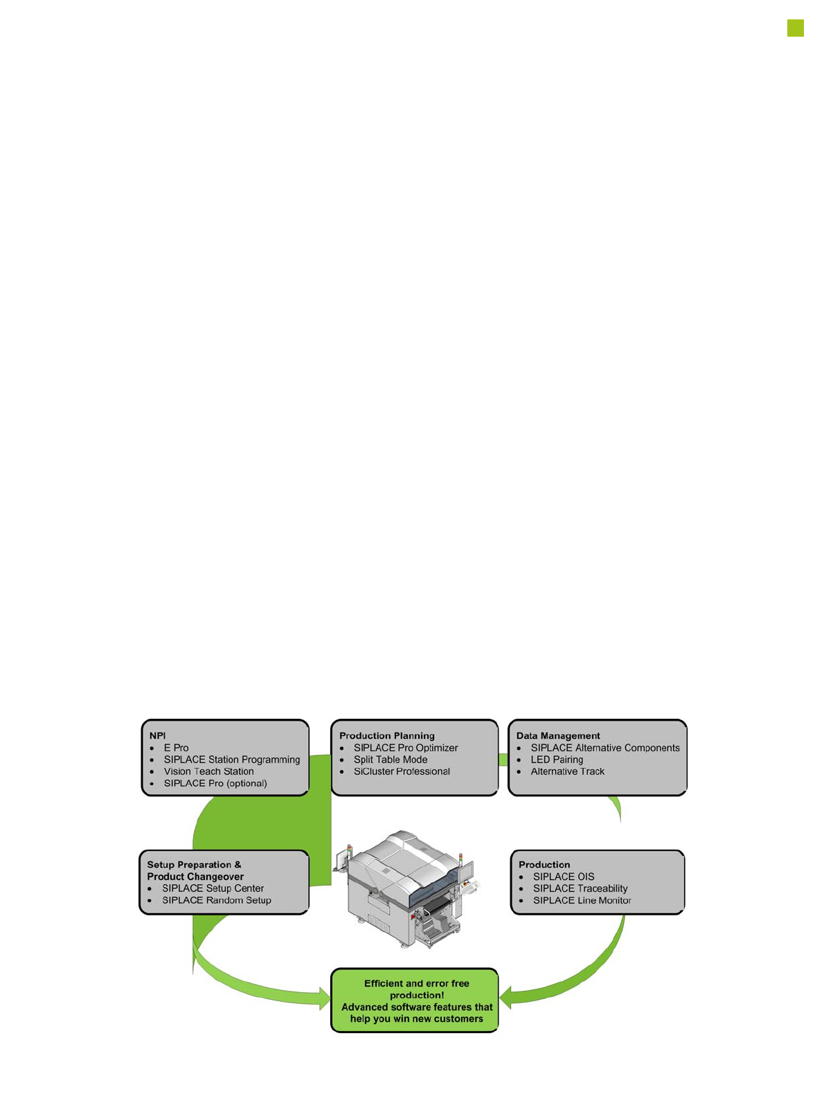
SIPLACE Software Suite
General
SIPLACE provides compre-
hensive solutions based on
modular software tools for
SMT machines, lines and
production management: the
SIPLACE software suite.
Product definition, optimi-
zation and line control
Fast, fault-free introduction
of products and optimum uti-
lization of production lines
are essential to maximize
production output. The pro-
grams from the SIPLACE
software suite allow you to
easily program products,
fine-tune the programs you
have created and then find
the balance for them within
your SMT production lines.
Production monitoring &
process control
To achieve the production
targets that are set, it is
important to constantly moni-
tor and check the production
facilities. The SIPLACE soft-
ware suite contains monitor-
ing products tailored to suit
the user group. These signal
immediately if limits are
exceeded on the machine or
the production line.
Setup verification &
traceability
Setup errors lead to series
errors. The user-friendly
SIPLACE software programs
help you to avoid such
errors, and thus ensure high
quality in your electronics
production.
The benefits of the
SIPLACE software suite at
a glance:
• User-friendly
• Simple operation
• Fast programming and
error detection
• Reduces changeover
times and stoppages
• Ensures optimum utiliza-
tion of your production
line's productivity
• Real-time information
from the production area
• Incredibly fast distribution
of information
• Optimum use of resources
• Timely notification when
production materials need
to be re-ordered
• Coordination of mainte-
nance
Note: The SIPLACE software suite tools will work with the optional SIPLACE Pro only (not with E Pro).