A10011-ASM-T45-EN-Spec-E_DMS.pdf - 第39页
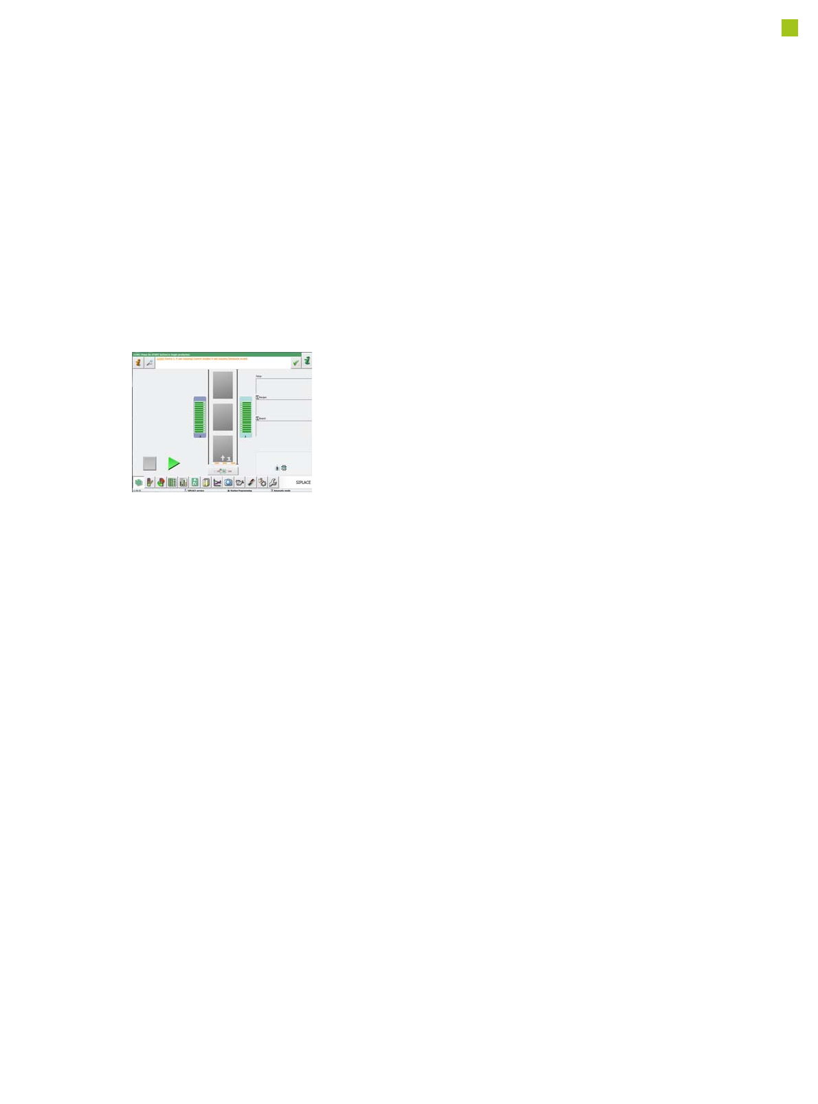
39 SIPLACE Software Suite SIPLACE Station Software The diversity of functions and applications in the station software version 709.1 illus - trates the extre me flexibility of the E by SIPLA CE. This software supports op…

38
SIPLACE Software Suite
Customer Benefit
SIPLACE Traceability
The SIPLACE Component
Verification System prevents
machine operators from
refilling wrong components
during production.
Together with a PCB Bar-
code Scanner the SIPLACE
Component Verification Sys-
tem allows the registration of
all incoming material during
the placement process. If
some of the placed compo-
nents subsequently turn out
to have faults, it can be
ascertained which other
PCBs are also fitted with
these faulty components,
while taking into account the
area of uncertainty around a
new reel.
As a result, it is possible to
recall only those boards that
really have faults. In addition,
the scope for providing evi-
dence to be used in liability
claims against component
suppliers is of benefit to the
customer.
Range of Functions :
• The end-user can specify
which data has to be regis-
tered for Traceability e.g.
Lot ID, Vendor ID, Date
Code etc. This information
can be encoded on a sin-
gle barcode or on multiple
barcodes onto the compo-
nent reel. Component
information can also be
verified after a single scan
of a "unique reel ID" which
links to the reels data set
in a database.
• The Component Level
Indicator counts the com-
ponent usage per track
during the placement pro-
cess. If a limit value is
exceeded, the operator is
forced to refill this track
and to register all relevant
data for Traceability.
• During production, the
traceability data can be
combined with the manu-
facturing order (Job ID)
and the product name, as
well as the time frame
during which the corre-
sponding manufacturing
order (Job ID) has been
produced.
Traceability Levels
Traceability data contain
information about the
batches/packaging units
used for placing components
on a board. There are vari-
ous ways of recording trace-
ability data.
• Level 1: Location/date-
related data entry
• Level 2: Production job/
recipe-related data entry
• Level 3: Board-related
data entry
• Level 4: Placement posi-
tion-related data entry
Line Monitor
SIPLACE Line Monitor pro-
vides an additional applica-
tion for the SIPLACE Setup
Center that displays the cur-
rent component levels for an
SIPLACE line.
The software offers guidance
to the line operator to:
• Ensure that materials are
provided from stock in
good time.
• Refill the material on the
line at the best possible
time.
SIPLACE Line Monitor thus
provides support for strate-
gies in which material is
drawn down from stock at the
production line as required
(deferred withdrawal of
materials).
Additionally, the software
provides an ergonomic pre-
sentation due to:
• Fully automated operation
(no intervention required
from the line operator)
• The largest possible rep-
resentation of information
and alarm states
• The display of information
directly on the line, namely
at the station computers
39
SIPLACE Software Suite
SIPLACE Station Software
The diversity of functions and
applications in the station
software version 709.1 illus-
trates the extreme flexibility
of the E by SIPLACE.
This software supports oper-
ators in their daily work, help-
ing them to simplify
processes on the machine
and to increase productivity
along the line. Four different
user levels ensure that each
operator has access to the
information and options
required to perform his spe-
cific work on the machine.
The benefits of the station
software 709.1 at a glance:
• Simple and innovative
user guidance, ideal for
both inexperienced users
(-> Smart GUI) and
experts
• Fast, direct access to all
machine functions and
systems, as required.
• "Best in Class" NPI fea-
tures
• Very user-friendly
• Highly robust in the place-
ment process
User-friendly "new product
introduction" process
The enhanced options for
new product introduction
(NPI) on the line is one of the
key features in the SIPLACE
station software 709.1.
New products need to be
produced error-free right
from the very first board. The
SIPLACE station software
satisfies this requirement by
supporting users during
product introduction with a
range of functions, including
the following.
Placement list at the station
The station always shows
the placement list for the
board currently being pro-
cessed. This placement list
includes the following infor-
mation:
• The placements in the
selected placement area
• The order in which the
components are placed
• The placement head
which places the compo-
nents
• The feeder module from
which the components are
picked up
• The status of the place-
ment position.
The status of the placement
positions can be changed
online at the station. If certain
components on the line are
to be omitted, the user can
delay placement of these
and perform it at a later time.
The status of the placement
position is divided into the
following categories (position
options):
•Place
• Skip (The placement posi-
tion will not be placed.
This status can either be
selected for the current
board or for the complete
job. This component will
then be ignored on the fol-
lowing boards until a new
job is sent to the line.)
• Postpone. (The compo-
nent will be placed at the
end of the placement
cycle.)
40
SIPLACE Software Suite
SIPLACE Station Software
Individual measurement data
The individual measurement
data determined by the
SIPLACE station software
(measurement contexts) can
be saved at the station. This
can be linked to the following
conditions (Vision measure-
ment options):
1. Unable to measure com-
ponent and measurement
data (measurement con-
texts) should be saved.
These measurement data
can then be used for opti-
mization purposes in a
subsequent analysis. As
with other optical inspec-
tion systems, pseudo
errors can be differentiat-
ed from other errors and
the affected component
shape can then be opti-
mized.
2. Vision measurement
logs should always be
written for this compo-
nent.
Whenever there is general
uncertainty about the
quality of a component,
the Vision logs can be writ-
ten for all components.
3. As soon as Vision errors
occur for the component,
the machine will stop.
If you want to avoid com-
ponent rejection, particu-
larly for very expensive
components, this option
can be used to correct all
measurement errors
occurring, without the
need for any rejections.
The machine waits with
the component, in front of
the camera, so that the
component can be
checked.
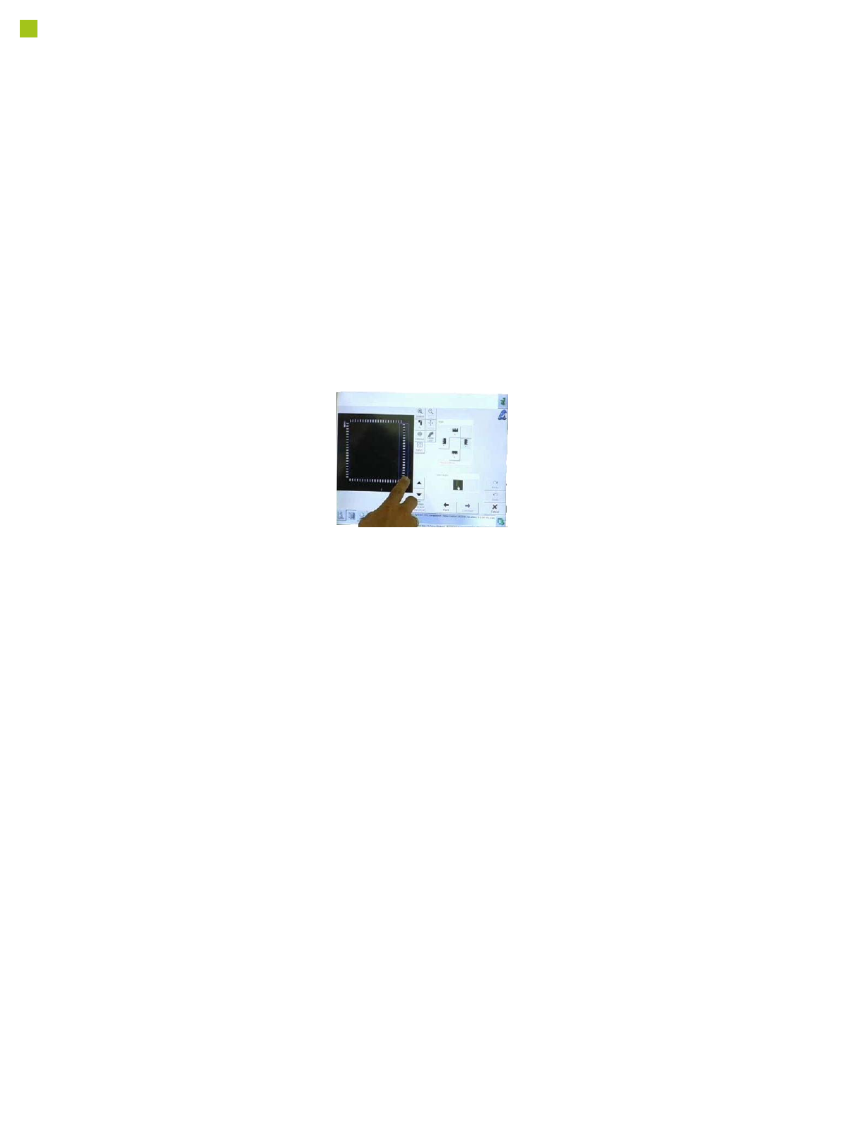
In addition, pickup and place
positions can be checked
with the PCB camera. This
makes 100% placement con-
trol possible in the machine.
Teaching components
Component shapes which
are not part of the standard
component shape library can
be generated using the
offline programming system
SIPLACE Pro, with the help
of data sheets, or with the
offline Vision teach station
and a sample component.
Alternatively, a component
shape can be marked as
incomplete and transferred
to the station with this status.
The description can be com-
pleted after the first pickup
run on the line.
After completion of the
description, a robustness
analysis can be performed at
the station, to ensure that
this component is always
recognized reliably, even
under different conditions.
You can also program the
placement positions on the
board in the station software.
This software provides
advanced support functions
which allow you, for exam-
ple, to combine images from
the PCB camera with data
from the placement program.
This boosts the productivity
significantly for production
environments with frequent
new production introductions
or product changeovers.
The SIPLACE station soft-
ware makes daily work eas-
ier for users
Many other features in the
station software make day-
to-day work easier for the
users and optimize the SMT
production processes.
• Calibration process con-
trol is fully integrated into
the SW
• Self-repair routines for
nozzles and feeder mod-
ules
• Self-determination of
feeder module cycle
• "Alarms" - at a glance
• "FaceDown" recognition
• Direct access to board
conveyor functions, such
as "nonstop board trans-
port".