A10011-ASM-T45-EN-Spec-E_DMS.pdf - 第8页
8 E by SIPLACE Placement Heads Overview Collect & Place principle The SIPLACE CP14/12/6 operates a ccording to the Collect & Place principle i.e. one cycle includes pickup or "collection" of 14/12/6 com…

7
E by SIPLACE
Machine Description
Easy operation
The innovations in the E by
SIPLACE go far beyond
technical details such as the
vision system, placement
heads, SIPLACE Smart-
Feeders E and software.
SIPLACE's developer paid
special attention to ease of
operation, user-friendliness
and lowest costs of opera-
tion. The E by SIPLACE's
software wizards and touch
panel make programming or
teaching new components as
easy as possible. And for
operation and cleaning and
checking,
SIPLACE has set up a spe-
cial E-Xperience area on the
Internet, where customers
will find checklists, docu-
ments and lots of videos for
training, operation and clean-
ing/checking. Instead of hir-
ing sometimes expensive
external technicians, cus-
tomers can train their own
teams to further reduce their
cost. Additionally our distri-
bution network with its global
network of partners also offer
what today's customers in
the mid-speed segment
want.
100% uptime with intelligent
feeder modules
The E by SIPLACE operates
with intelligent feeder mod-
ules, which simplify the
upgrade and conversion
tasks significantly. For exam-
ple, the SIPLACE Smart-
Feeder E modules can even
be converted during produc-
tion, thereby reducing
machine stoppages.
With these advanced fea-
tures, SIPLACE has estab-
lished a class of its own for
SMT production, which ranks
way above all other place-
ment solutions on the mar-
ket.
Further information
If you're interested in further
technical details, if you'd like
to contact us directly, or if
you'd like to enquire about
the appointed distributor for
your region, please visit us at
www.e-by-siplace.com
.

8
E by SIPLACE Placement Heads
Overview
Collect&Place principle
The SIPLACE CP14/12/6
operates according to the
Collect&Place principle i.e.
one cycle includes pickup or
"collection" of 14/12/6 com-
ponents, their optical center-
ing on the board and their
rotation into the required
placement angle and posi-
tion. They are then placed
gently and accurately onto
the PCB. This principle is
particularly suitable for high-
speed placement of standard
components.
Pick&Place principle
The high-precision SIPLACE
TwinHead or P&P module
functions according to the
Pick&Place principle. One or
two components are picked
up by the SIPLACE Twin-
Head/PP, optically centered
on the way to the placement
position and then rotated into
the required placement
angle. This principle is ideally
suitable for fast and precise
placement of special compo-
nents in the fine pitch or
super fine pitch field, plus
complex and heavy compo-
nents which may need grip-
pers.
Control and self-learning
functions
The reliability of the
SIPLACE placement heads
can be enhanced even fur-
ther with various checking
and self-learning functions.
• Component sensor
Checks the presence of
the components on the
nozzle before the pickup
and placement process
• Digital camera
Checks the position of
each component on the
nozzle. This check is per-
formed in a single step,
with no extra time involved
but with optimum scan-
ning of each individual
component.
• Force sensor
Monitors the prescribed
component set-down
force.
The sensor stop proce-
dure enables compensa-
tion of height differences
during pickup and PCB
warpage during place-
ment.
• Vacuum sensor
Checks whether the com-
ponent was correctly
picked up or placed.
Camera Configurations
Head 1 Camera Optional Head 2 Standard Camera Optional
a
a) Flip-Chip Camera, Type 25 GigE as additional stationary camera is possible
CP14 Type 23 GigE -- -- -- --
CP12 Type 30 GigE -- -- -- --
CP12 Type 30 GigE -- PP Type 36 GigE Type 33 GigE
Type 25 GigE
CP6 Type 30 GigE -- PP Type 36 GigE Type 33 GigE
Type 25 GigE
-- -- -- TH Type 36 GigE Type 33 GigE
Type 25 GigE
9
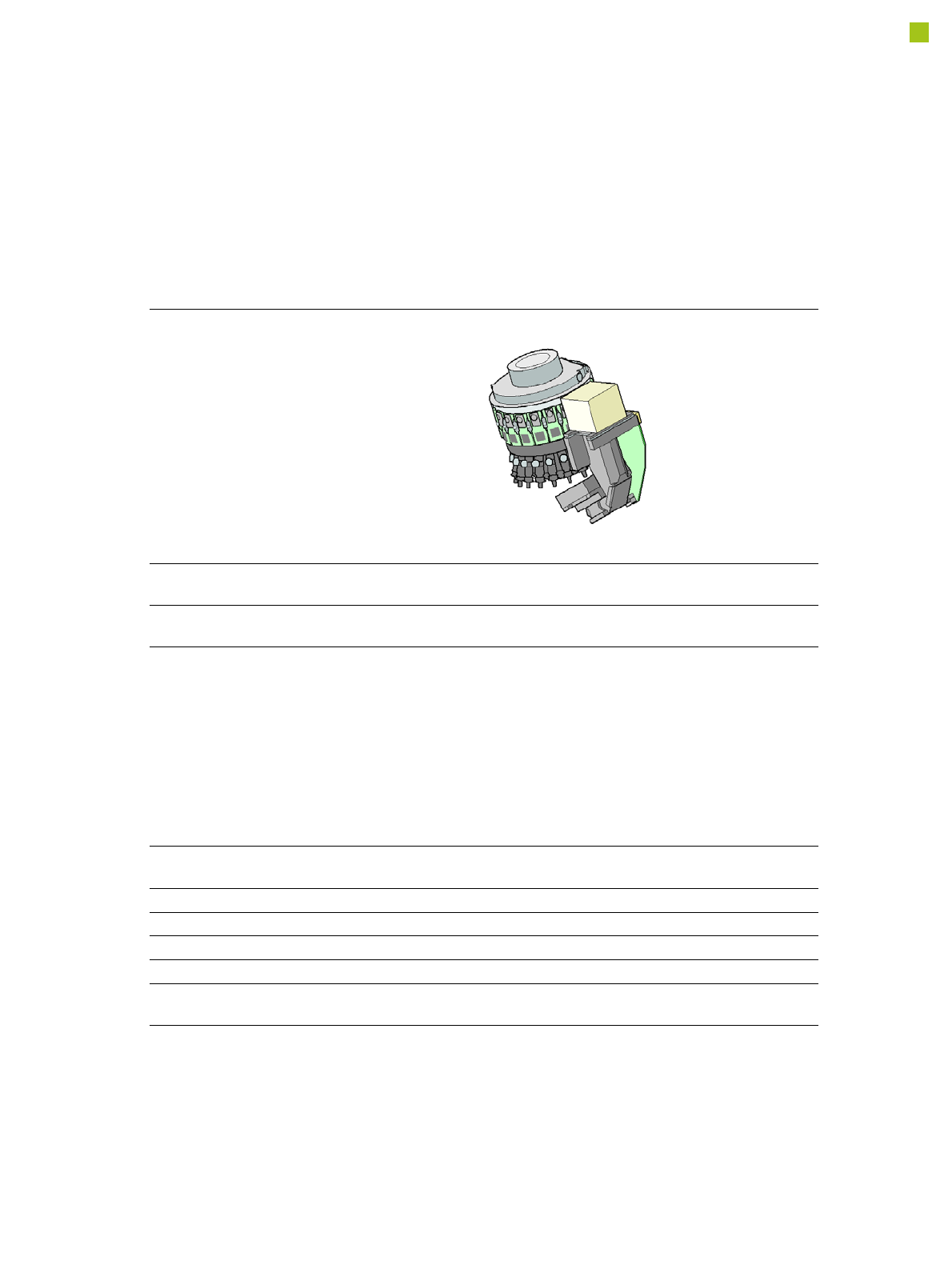
Placement Heads
SIPLACE CP14
SIPLACE CP14
with component camera type
23 GigE
Component range
a
a) Please note that the placeable component range is also affected by the pad geometry, the customer-spe-
cific standards, the component packaging tolerances and the component tolerances.
01005 to 2220, Melf, SOT,
SOD
Component spec.
Max. height
Min. lead pitch
Min. lead width
Min. ball pitch
Min. ball diameter
Min. dimensions
Max. dimensions
Max. weight
4 mm
0.25 mm
0.1 mm
0.4 mm
0.2 mm
0.4 mm x 0.2 mm
6 mm x 6 mm
1.0 g
Programmable set-down
force
1.3 - 4.5 N
Nozzle types 4xxx
X/Y accuracy
b
b) The SIPLACE accuracy value is measured during the machine acceptance tests. It corresponds to the
conditions set out in the SIPLACE scope of service and supply.
± 41 µm/3σ
Angular accuracy ± 0.5° / 3σ
Illumination level 5
Possible illumination
level settings
256