A10011-ASM-T45-EN-Spec-E_DMS.pdf - 第9页
9 Placement Heads SIPLACE CP14 SIPLACE CP14 with compone nt camera type 23 GigE Component range a a) Please note that the placeable component r ange is also affected by the pad geometr y, the custo mer-spe - cific standa…

8
E by SIPLACE Placement Heads
Overview
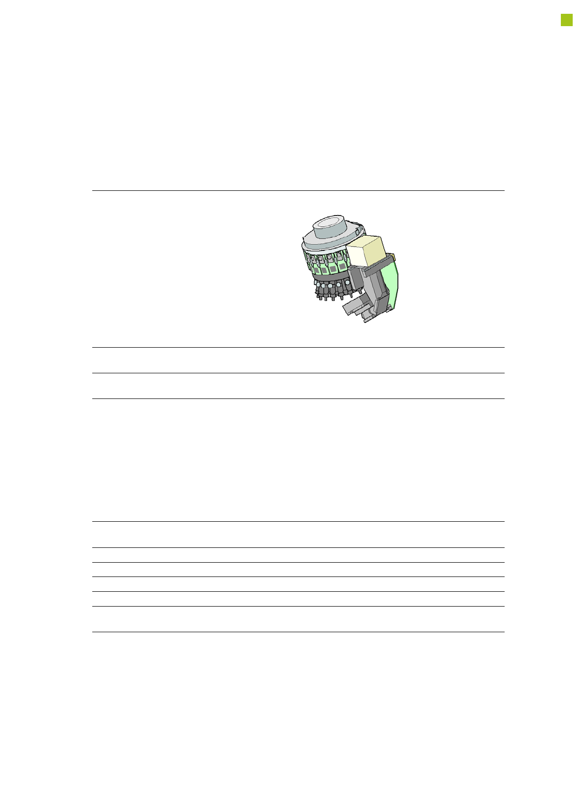
Collect&Place principle
The SIPLACE CP14/12/6
operates according to the
Collect&Place principle i.e.
one cycle includes pickup or
"collection" of 14/12/6 com-
ponents, their optical center-
ing on the board and their
rotation into the required
placement angle and posi-
tion. They are then placed
gently and accurately onto
the PCB. This principle is
particularly suitable for high-
speed placement of standard
components.
Pick&Place principle
The high-precision SIPLACE
TwinHead or P&P module
functions according to the
Pick&Place principle. One or
two components are picked
up by the SIPLACE Twin-
Head/PP, optically centered
on the way to the placement
position and then rotated into
the required placement
angle. This principle is ideally
suitable for fast and precise
placement of special compo-
nents in the fine pitch or
super fine pitch field, plus
complex and heavy compo-
nents which may need grip-
pers.
Control and self-learning
functions
The reliability of the
SIPLACE placement heads
can be enhanced even fur-
ther with various checking
and self-learning functions.
• Component sensor
Checks the presence of
the components on the
nozzle before the pickup
and placement process
• Digital camera
Checks the position of
each component on the
nozzle. This check is per-
formed in a single step,
with no extra time involved
but with optimum scan-
ning of each individual
component.
• Force sensor
Monitors the prescribed
component set-down
force.
The sensor stop proce-
dure enables compensa-
tion of height differences
during pickup and PCB
warpage during place-
ment.
• Vacuum sensor
Checks whether the com-
ponent was correctly
picked up or placed.
Camera Configurations
Head 1 Camera Optional Head 2 Standard Camera Optional
a
a) Flip-Chip Camera, Type 25 GigE as additional stationary camera is possible
CP14 Type 23 GigE -- -- -- --
CP12 Type 30 GigE -- -- -- --
CP12 Type 30 GigE -- PP Type 36 GigE Type 33 GigE
Type 25 GigE
CP6 Type 30 GigE -- PP Type 36 GigE Type 33 GigE
Type 25 GigE
-- -- -- TH Type 36 GigE Type 33 GigE
Type 25 GigE
9
Placement Heads
SIPLACE CP14
SIPLACE CP14
with component camera type
23 GigE
Component range
a
a) Please note that the placeable component range is also affected by the pad geometry, the customer-spe-
cific standards, the component packaging tolerances and the component tolerances.
01005 to 2220, Melf, SOT,
SOD
Component spec.
Max. height
Min. lead pitch
Min. lead width
Min. ball pitch
Min. ball diameter
Min. dimensions
Max. dimensions
Max. weight
4 mm
0.25 mm
0.1 mm
0.4 mm
0.2 mm
0.4 mm x 0.2 mm
6 mm x 6 mm
1.0 g
Programmable set-down
force
1.3 - 4.5 N
Nozzle types 4xxx
X/Y accuracy
b
b) The SIPLACE accuracy value is measured during the machine acceptance tests. It corresponds to the
conditions set out in the SIPLACE scope of service and supply.
± 41 µm/3σ
Angular accuracy ± 0.5° / 3σ
Illumination level 5
Possible illumination
level settings
256

10
Placement Heads
SIPLACE CP12
SIPLACE CP12
with component camera type 30 GigE
Range of components
a
a) Please note that the component range that can be placed is also affected by the pad geometry, the customer-specific
standards and the packaging tolerances.
01005 to flip-chip, bare die, PLCC44, BGA, µBGA, TSOP, QFP, SO to
SO32, DRAM
Component specification
Max. height
Min. lead pitch
Min. lead width
Min. ball pitch
Min. ball diameter
Min. dimensions
Max. dimensions
b
Max. weight
b) For high volume 01005-placement it is recommended to equip the CP12 with its optional 01005-package that con-
tains special nozzles and low force segments.
8.5 mm
c
0.3 mm
0.15 mm
0.25 mm
0.14 mm
0.4 mm x 0.2 mm
18.7 mm x 18.7 mm
2 g
c) 8.5 mm on Flex machines, 7.5 mm on Speed machines.
Nozzle types 30xx
X/Y accuracy
d
d) The accuracy value was measured using the vendor-neutral IPC standard.
± 41 μm/3σ
Angular accuracy ± 0.5°/3σ
Component range 98.5%
Illumination levels 5
Possible illumination level
setting
256