WaferTransportSolutionManual.pdf - 第101页
INSTALLATION EQUIPMENT INSTALLATION Chapter Issue 1 Aug 11 Wafer Transport Solutio n 3.25 19. T est at the lowest point (described by the pa llet rock). At points found to be low , which could affect p allet rock; make a…
INSTALLATION
EQUIPMENT INSTALLATION
3.24 Wafer Transport Solution Chapter Issue 1 Aug 11
NOTE
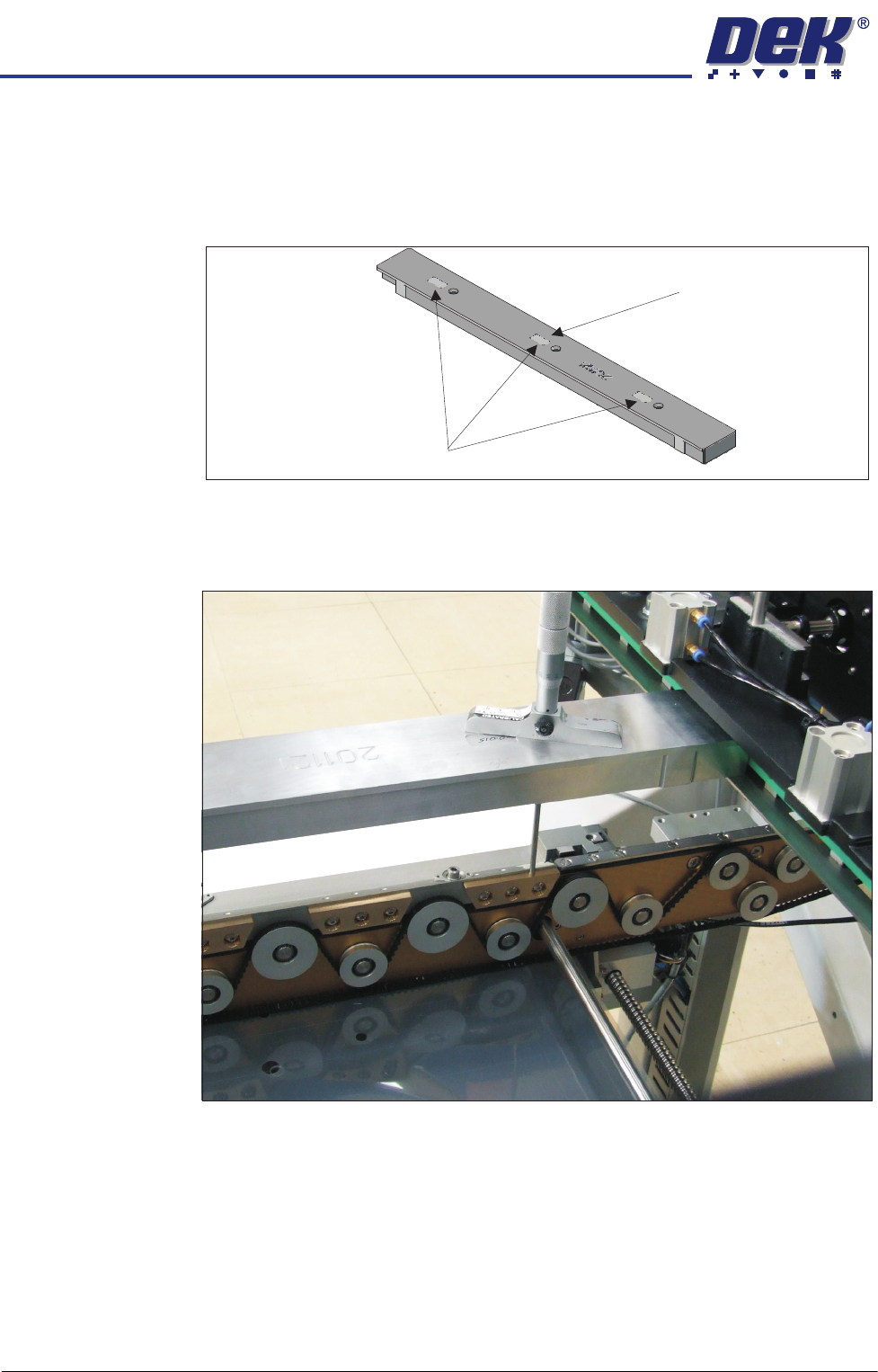
All setting bars are marked with unique readings expressing the bar’s
flatness. The centre reading is always zero, the other readings are relative
to the centre. These markings are known as the setting bar flatness
calibration figures.
17. Remove the depth micrometer.
18. Insert the depth micrometer into the left hole of the setting bar. The depth
micrometer tip contacts the left hand pallet support block.
Setting Bar Flatness Calibration Figures
Centre is Zero (0.00)
INSTALLATION
EQUIPMENT INSTALLATION
Chapter Issue 1 Aug 11 Wafer Transport Solution 3.25
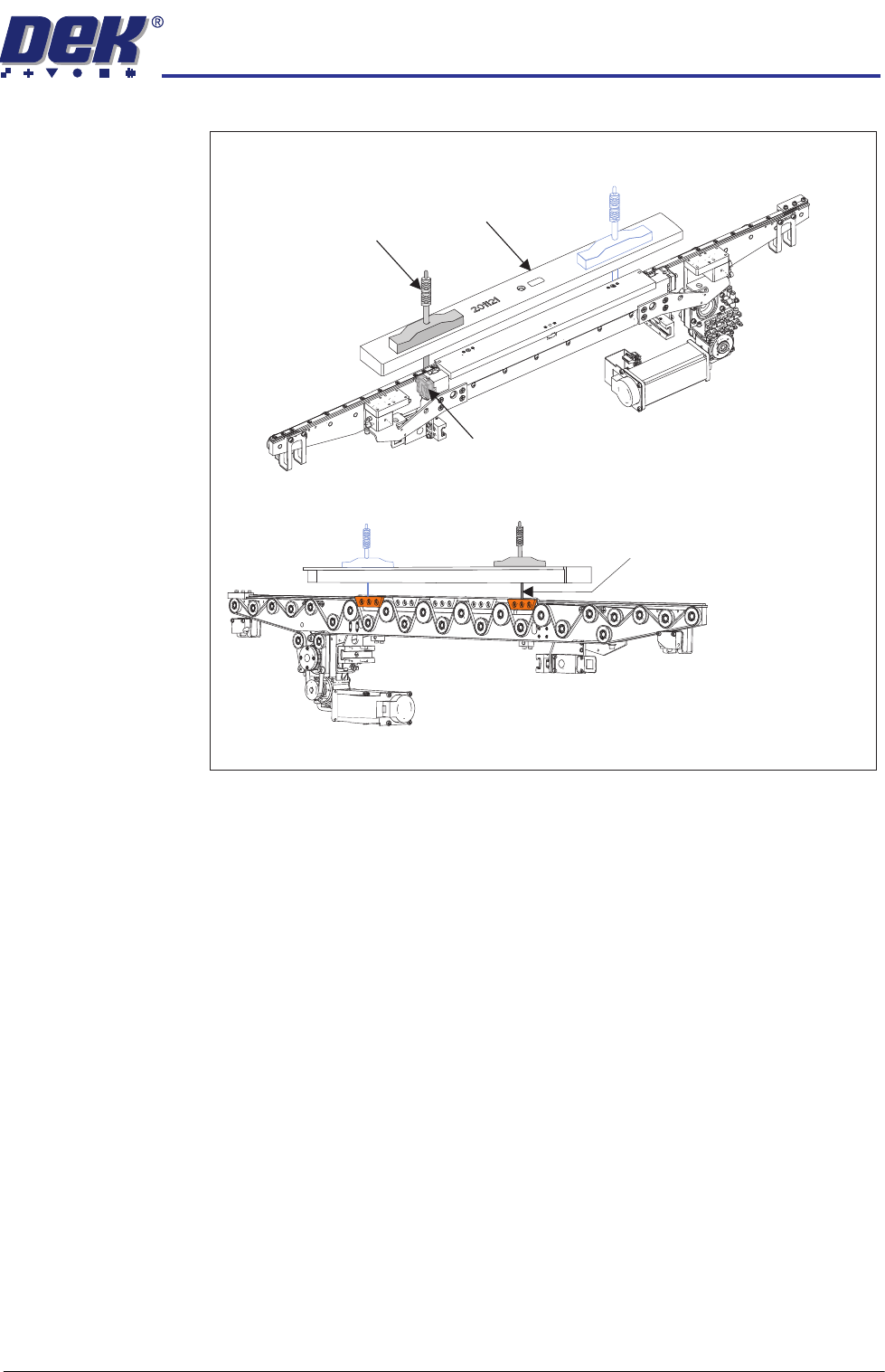
19. Test at the lowest point (described by the pallet rock).
At points found to be low, which could affect pallet rock; make adjustments
to the rail height adjusters.
View on Front Left Quarter of the Front Rail
View on the Rear of the Front Rail
Depth Micrometer
Depth Micrometer
(Location 2)
Rail Height Adjuster
Setting Bar
Micrometer readings taken
from the top surface of the
pallet support blocks as shown
INSTALLATION
EQUIPMENT INSTALLATION
3.26 Wafer Transport Solution Chapter Issue 1 Aug 11
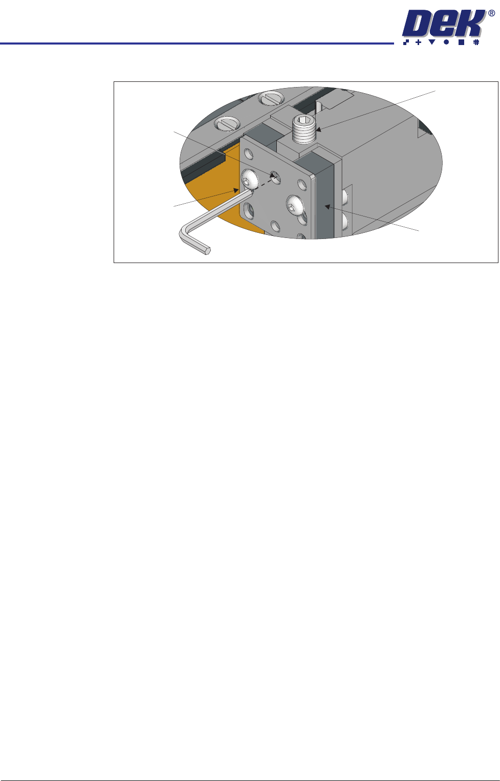
20. Slacken off the rail height adjuster lock screws.
21. Adjust the set screws to raise or lower the rail, until the reading on the depth
micrometer is the same as that of the reading made with the depth microm-
eter on the tooling pin, ± the setting bar calibration figure.
22. Repeat the steps above to make adjustments to other low points.
23. Tighten all lock screws and confirm the setting.
24. Carry out the procedure for the rear rail; if needed.
25. Reload the pallet and shim and recheck for any rocking; retest for the low
point and adjust if required.
26. Restore the E Stop.
27. Close the front printhead cover.
28. Press the System Button.
29. Select Exit.
30. Select Rail System.
31. Select Select Module.
32. Select Toggle Heavy Rail Drop. This holds the pallet in the correct location
without clamping and lowers the belts.
33. Open the printhead front cover.
34. Place the setting bar across the top of both rails front to back.
35. Using the depth micrometer through the setting bar, as previously described,
check all four corners of the pallet. The reading on the depth micrometer is
the same as that of the reading made with the depth micrometer on the
tooling pin, ± the setting bar calibration figure. The co-planarity of the
system and customer pallet should be sufficient to match the process and
tooling used.
36. If required, adjust the rail height, and recheck the settings.
37. Remove all tooling.
38. Remove the two setting rods.
39. Close the front printhead cover.
40. Press the System button.
View on Left Front Rail Clamp
Set Screw
Rail Clamp
Linear Bearing
Height Adjuster
Lock Screw