WaferTransportSolutionManual.pdf - 第103页
INSTALLATION EQUIPMENT INSTALLATION Chapter Issue 1 Aug 11 Wafer Transport Solutio n 3.27 41. Select Exit . 42. Using Decr . or Incr . . 43. Select the Rising T able . 44. Select Home Rising T able . Run the diagnostic. …
INSTALLATION
EQUIPMENT INSTALLATION
3.26 Wafer Transport Solution Chapter Issue 1 Aug 11
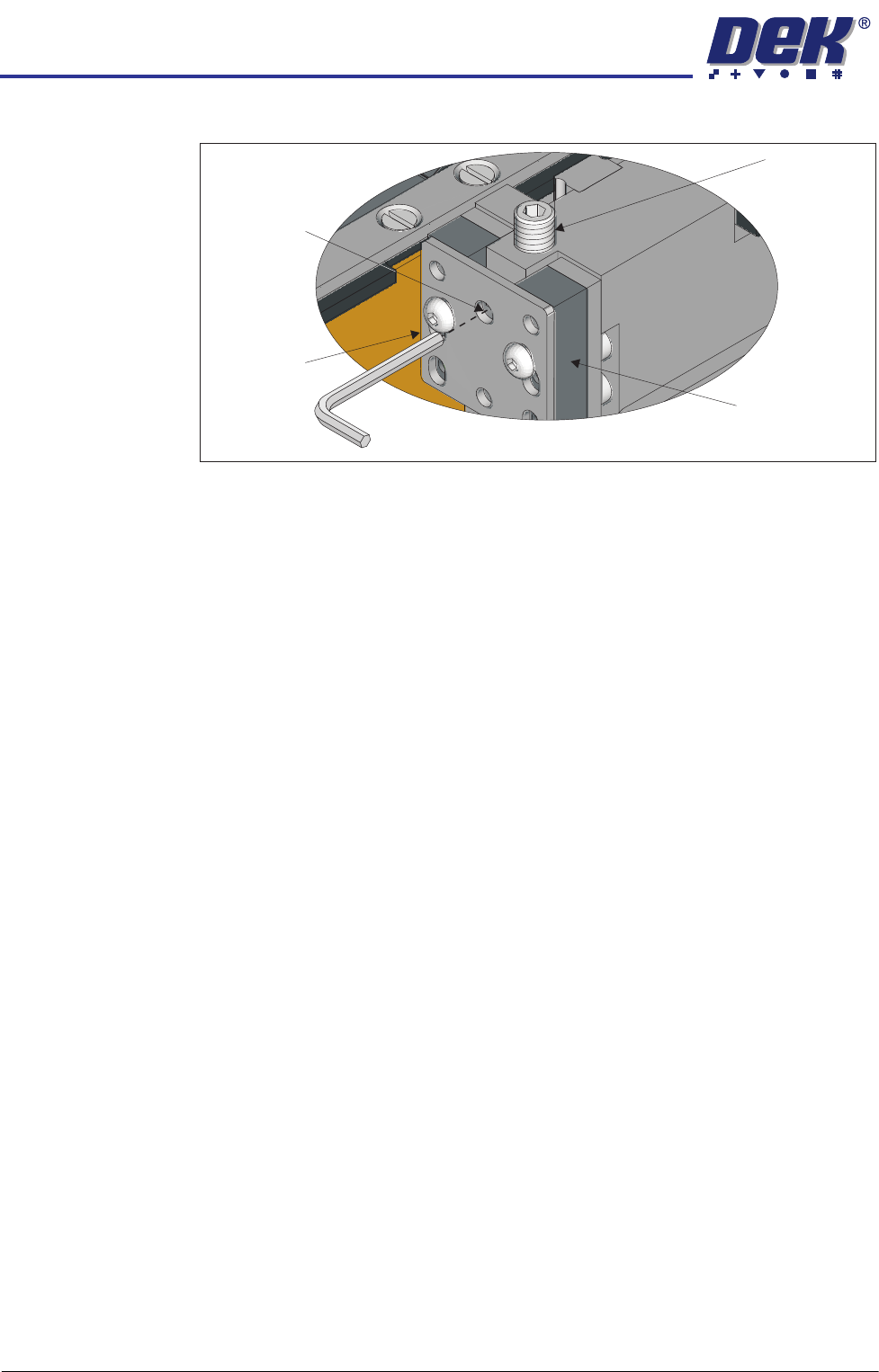
20. Slacken off the rail height adjuster lock screws.
21. Adjust the set screws to raise or lower the rail, until the reading on the depth
micrometer is the same as that of the reading made with the depth microm-
eter on the tooling pin, ± the setting bar calibration figure.
22. Repeat the steps above to make adjustments to other low points.
23. Tighten all lock screws and confirm the setting.
24. Carry out the procedure for the rear rail; if needed.
25. Reload the pallet and shim and recheck for any rocking; retest for the low
point and adjust if required.
26. Restore the E Stop.
27. Close the front printhead cover.
28. Press the System Button.
29. Select Exit.
30. Select Rail System.
31. Select Select Module.
32. Select Toggle Heavy Rail Drop. This holds the pallet in the correct location
without clamping and lowers the belts.
33. Open the printhead front cover.
34. Place the setting bar across the top of both rails front to back.
35. Using the depth micrometer through the setting bar, as previously described,
check all four corners of the pallet. The reading on the depth micrometer is
the same as that of the reading made with the depth micrometer on the
tooling pin, ± the setting bar calibration figure. The co-planarity of the
system and customer pallet should be sufficient to match the process and
tooling used.
36. If required, adjust the rail height, and recheck the settings.
37. Remove all tooling.
38. Remove the two setting rods.
39. Close the front printhead cover.
40. Press the System button.
View on Left Front Rail Clamp
Set Screw
Rail Clamp
Linear Bearing
Height Adjuster
Lock Screw

INSTALLATION
EQUIPMENT INSTALLATION
Chapter Issue 1 Aug 11 Wafer Transport Solution 3.27
41. Select Exit.
42. Using Decr. or Incr..
43. Select the Rising Table.
44. Select Home Rising Table. Run the diagnostic.
45. Open the printhead front cover.
Top Plate
Adjustment
NOTE
The precision pallet, shim, rail top plates and setting bar are all manufactured
to a high degree of flatness and are susceptible to surface flaws that can
degrade their function. In the following procedure hard tooling is used in contact
with these surfaces which may cause markings or more significant damage, if
not handled carefully. Tooling used must be clean and blemish free. All effort
must be made to avoid dragging, dropping or knocking tools on the exposed
surfaces.
1. Ensure that the screen has been removed from the printer.
2. Ensure that the pallet and shim have been removed from the printer.
3. Select Setup Product.
4. Select Board Length Board Width.
5. Select Board Width. Set the board width to match the pallet.
6. Select Board Length. Set the board length to match the pallet.
7. Select Accept.
8. Select Back.
9. Select Maintenance.
10. Select Diagnostics.
11. Select Rail System.
12. Select Select Module.
13. Select Toggle Heavy Rail Drop.
14. Select Run Diagnost..
15. Open the printhead front cover. The software pauses and displays the
System Error - System Suspended While Covers Open Warning.
16. Move the print carriage to the rear of the printer.
17. Load the pallet and shim into the print area.
18. Carefully run a finger along the length of the top plates (front and rear) and
check for any areas where adjustment is needed.
19. Loosen the six locking screws (on each rail) and adjust the three adjustment
screws on the top plates so that the top plate matches the pallet height.
20. Tighten the locking screws.
INSTALLATION
EQUIPMENT INSTALLATION
3.28 Wafer Transport Solution Chapter Issue 1 Aug 11
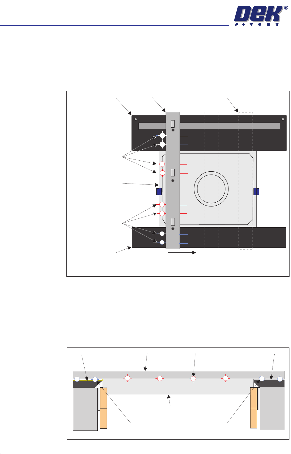
21. Carefully place the setting bar across both rails covering the pallet and shim
at three points:
• Left hand edge
• Centre
• Right hand edge
22. A 0.05mm feeler gauge is used to check that any gap, between the top
plates and the setting bar, is not greater than 0.05mm. Measurements
should be made at similar locations to those shown in the graphic above.
For each location, slide a feeler gauge between the setting bar and: the top
plates, the pallet and the shim. On the top plates, the gap should be as
detailed below (outer target areas [1,2,7&8]). For the areas between the
setting bar and the pallet/shim (inner target areas [3,4,5&6]) it should not be
possible to insert the feeler gauge.
23. Make fine adjustment to the rail height adjustment set screws to give a flat
Pallet Shimand
Carefully position the setting bar at the left, centre and
right positions to make the measurements.
Front Transport Rail
Rear Transport Rail
Setting Bar
Measurement
Locations
(both sides of the bar)
Measurement
Locations
(both sides of the bar)
Setting Bar (at end location)
1
2
3
4
5
6
7
8
View on Right Hand Side of Rails
Customer Pallet and Shim
Setting Bar
Top Plate Top Plate
Gap = 0.05mm
Gap < 0.05mm
Gap = 0.05mm
Front Rail
Rear Rail
1
2
3
4
5
6
7
8