WaferTransportSolutionManual.pdf - 第104页
INSTALLATION EQUIPMENT INSTALLATION 3.28 Wafer Transport Solutio n Chapter Issue 1 Aug 11 21. Carefully place the setting bar across both rails covering the pallet and shim at three points: • Left hand ed ge • Centre • R…

INSTALLATION
EQUIPMENT INSTALLATION
Chapter Issue 1 Aug 11 Wafer Transport Solution 3.27
41. Select Exit.
42. Using Decr. or Incr..
43. Select the Rising Table.
44. Select Home Rising Table. Run the diagnostic.
45. Open the printhead front cover.
Top Plate
Adjustment
NOTE
The precision pallet, shim, rail top plates and setting bar are all manufactured
to a high degree of flatness and are susceptible to surface flaws that can
degrade their function. In the following procedure hard tooling is used in contact
with these surfaces which may cause markings or more significant damage, if
not handled carefully. Tooling used must be clean and blemish free. All effort
must be made to avoid dragging, dropping or knocking tools on the exposed
surfaces.
1. Ensure that the screen has been removed from the printer.
2. Ensure that the pallet and shim have been removed from the printer.
3. Select Setup Product.
4. Select Board Length Board Width.
5. Select Board Width. Set the board width to match the pallet.
6. Select Board Length. Set the board length to match the pallet.
7. Select Accept.
8. Select Back.
9. Select Maintenance.
10. Select Diagnostics.
11. Select Rail System.
12. Select Select Module.
13. Select Toggle Heavy Rail Drop.
14. Select Run Diagnost..
15. Open the printhead front cover. The software pauses and displays the
System Error - System Suspended While Covers Open Warning.
16. Move the print carriage to the rear of the printer.
17. Load the pallet and shim into the print area.
18. Carefully run a finger along the length of the top plates (front and rear) and
check for any areas where adjustment is needed.
19. Loosen the six locking screws (on each rail) and adjust the three adjustment
screws on the top plates so that the top plate matches the pallet height.
20. Tighten the locking screws.
INSTALLATION
EQUIPMENT INSTALLATION
3.28 Wafer Transport Solution Chapter Issue 1 Aug 11
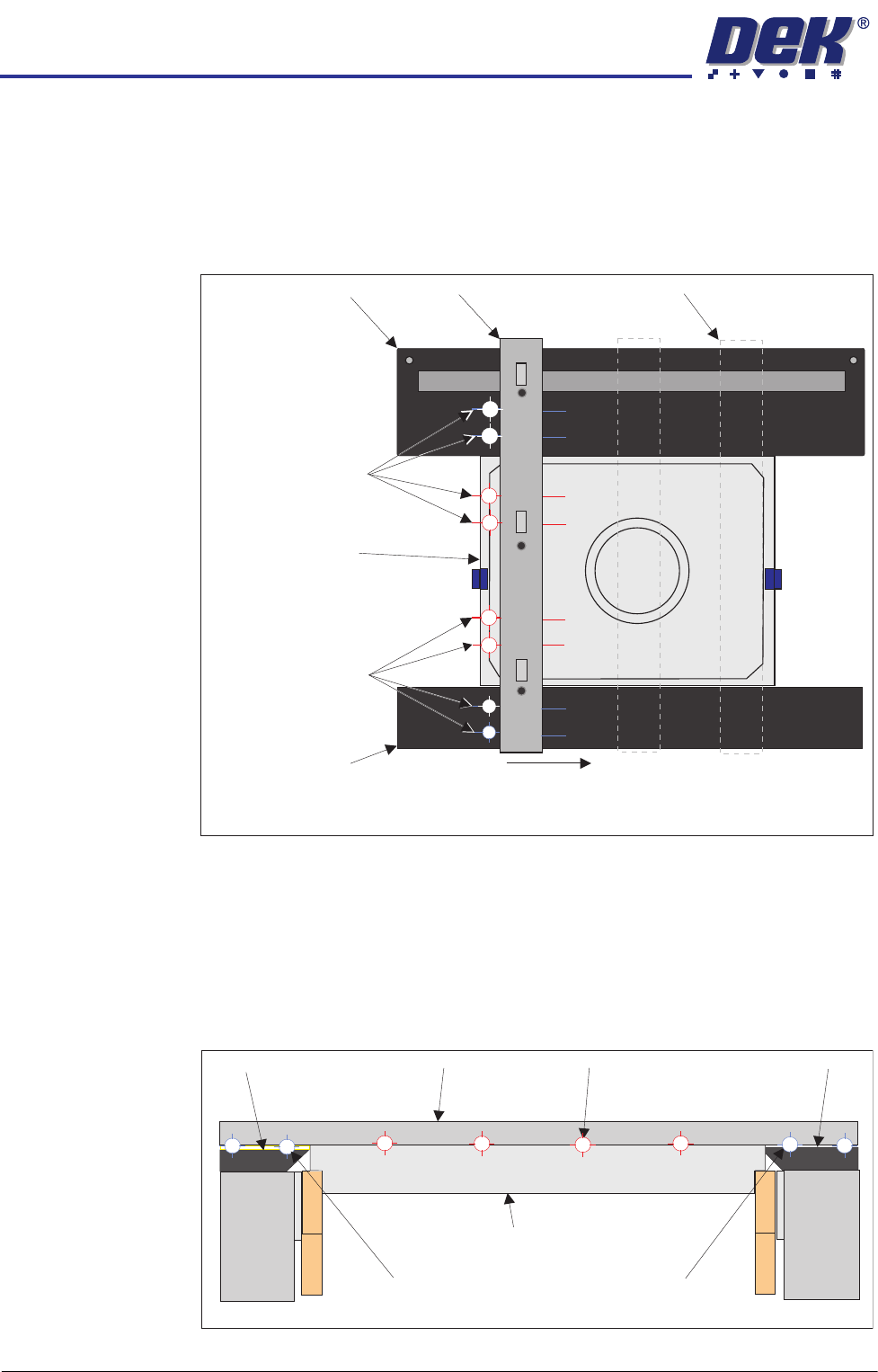
21. Carefully place the setting bar across both rails covering the pallet and shim
at three points:
• Left hand edge
• Centre
• Right hand edge
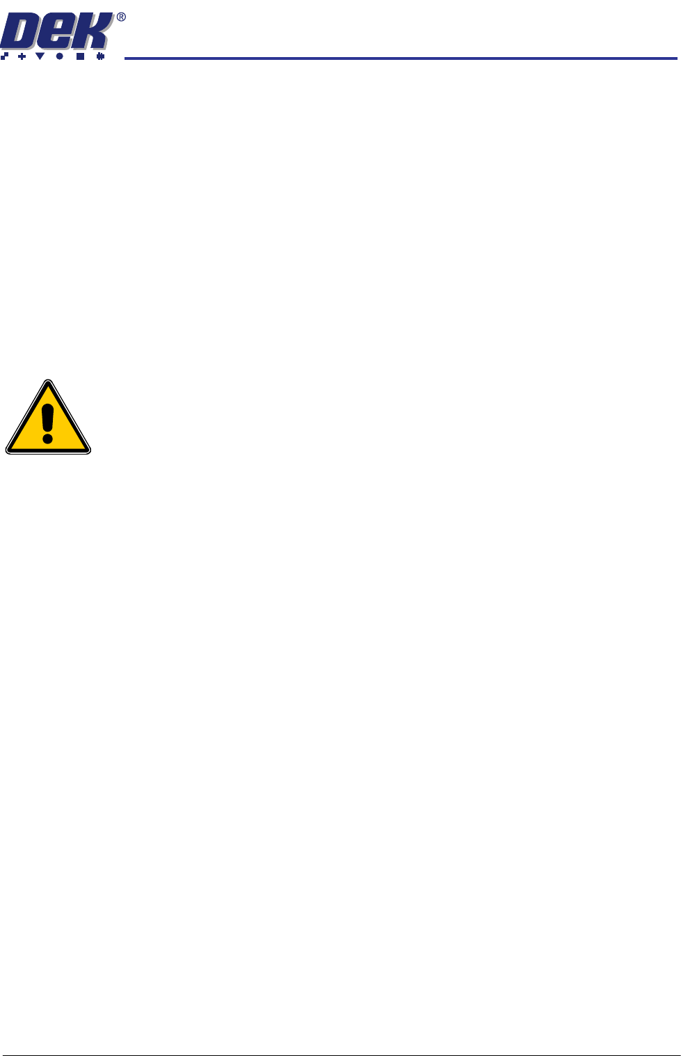
22. A 0.05mm feeler gauge is used to check that any gap, between the top
plates and the setting bar, is not greater than 0.05mm. Measurements
should be made at similar locations to those shown in the graphic above.
For each location, slide a feeler gauge between the setting bar and: the top
plates, the pallet and the shim. On the top plates, the gap should be as
detailed below (outer target areas [1,2,7&8]). For the areas between the
setting bar and the pallet/shim (inner target areas [3,4,5&6]) it should not be
possible to insert the feeler gauge.
23. Make fine adjustment to the rail height adjustment set screws to give a flat
Pallet Shimand
Carefully position the setting bar at the left, centre and
right positions to make the measurements.
Front Transport Rail
Rear Transport Rail
Setting Bar
Measurement
Locations
(both sides of the bar)
Measurement
Locations
(both sides of the bar)
Setting Bar (at end location)
1
2
3
4
5
6
7
8
View on Right Hand Side of Rails
Customer Pallet and Shim
Setting Bar
Top Plate Top Plate
Gap = 0.05mm
Gap < 0.05mm
Gap = 0.05mm
Front Rail
Rear Rail
1
2
3
4
5
6
7
8
INSTALLATION
EQUIPMENT INSTALLATION
Chapter Issue 1 Aug 11 Wafer Transport Solution 3.29
surface.
24. On completion, the locking screws can be tightened to lock the position.
25. Use the setting bar and feeler gauge to recheck flatness and adjust if
required.
26. Replace the sphere dump tray into the rear transport rail.
27. Wind down the two safety screws which support the rear of the rear top
plate. They should just contact the lift cylinder arms.
28. Close the printhead cover.
29. Replace safety covers.
30. If after printing, using these settings, the results are accurate; there is no
need to carry out the accuracy check.
Accuracy Check
WARNING
HEAVY OBJECT. EXTREME CAUTION SHOULD BE EXERCISED WHEN
MANUALLY HANDLING HEAVY ITEMS INTO OR OUT OF THE MACHINE.
NOTE
The precision pallet, shim, rail top plates and setting bar are all manufactured
to a high degree of flatness and are susceptible to surface flaws that can
degrade their function. In the following procedure hard tooling is used in contact
with these surfaces which may cause markings or more significant damage, if
not handled carefully. Tooling used must be clean and blemish free. All effort
must be made to avoid dragging, dropping or knocking tools on the exposed
surfaces.
The intended maximum flatness of the top plate relative to the shim is 50
microns(±0.025mm). The step from the shim to the top plate is +/- 0.01mm.
1. Ensure that the reference check has been carried out before proceeding.
2. Ensure that the DTI gauge is within its calibration date and the contact
surface of the gauge is clean and free of imperfections.
3. Remove the printer’s side safety covers and ensure reasonable access to
the area behind the rear rail.
4. Assemble the gauge on its stand so the probe is acting vertically downward
and the arm is extended to approximately 60 to 70mm from the edge of the
stand.
5. Place the gauge assembly onto the engraved calibration surface of the
setting bar.
6. Adjust the gauge probe so that it floats freely on the surface of the setting
bar top surface.
7. Zero the gauge.
NOTE
The above action calibrates the gauge needle-to-base zero position.
8. Carefully move the gauge assembly around the setting bar to confirm that