WaferTransportSolutionManual.pdf - 第108页
INSTALLATION EQUIPMENT INSTALLATION 3.32 Wafer Transport Solutio n Chapter Issue 1 Aug 11 a gap between the point of each screw and the lift cylinder arms. 25. Repeat S teps 20 and 2 1 to check the top plates remain with…
INSTALLATION
EQUIPMENT INSTALLATION
Chapter Issue 1 Aug 11 Wafer Transport Solution 3.31
procedure for the rear top plate.
22. Place the gauge probe on the shim; the reading should be zero. Repeat the
step above along the 0.01mm line.
23. Make small adjustments, as required, to the front and rear top plate adjust-
ment screws, (do not unlock the associated locking screws) in the areas
which display out of tolerance results; only minor adjustments are neces-
sary.
24. Wind the safety screws back down; use an 0.05mm feeler gauge to maintain
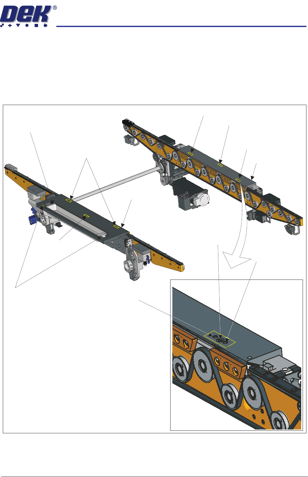
Adjustment (1) Screws (2)and Locking
Sphere Dump Tray
Rear Top Plate
Front Top Plate
Locking Screw
Locking Screw
Adjustment (1) and Locking Screws (2)
Adjustment (1) Screw
Adjustment (1) Screw
Safety Screws (2)
Adjustment (1)
Locking
and
Screws (2)
Adjustment Screw
INSTALLATION
EQUIPMENT INSTALLATION
3.32 Wafer Transport Solution Chapter Issue 1 Aug 11
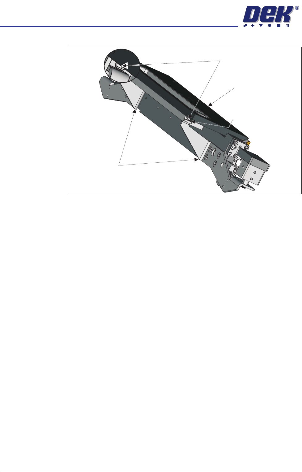
a gap between the point of each screw and the lift cylinder arms.
25. Repeat Steps 20 and 21 to check the top plates remain within the stated
tolerance.
26. Remove the paper sheet and the gauge and the stand.
27. Close the printhead front cover.
28. Reset the E Stop.
29. Press the System button.
30. Select Toggle Board Clamps.
31. Open the printhead front cover.
32. Remove the pallet and shim.
33. Close the printhead front cover.
34. Press the System button.
Lift Cylinder Arm
Maintain Gap0.05mm
Safety Screws
Rear Top Plate
INSTALLATION
EQUIPMENT INSTALLATION
Chapter Issue 1 Aug 11 Wafer Transport Solution 3.33
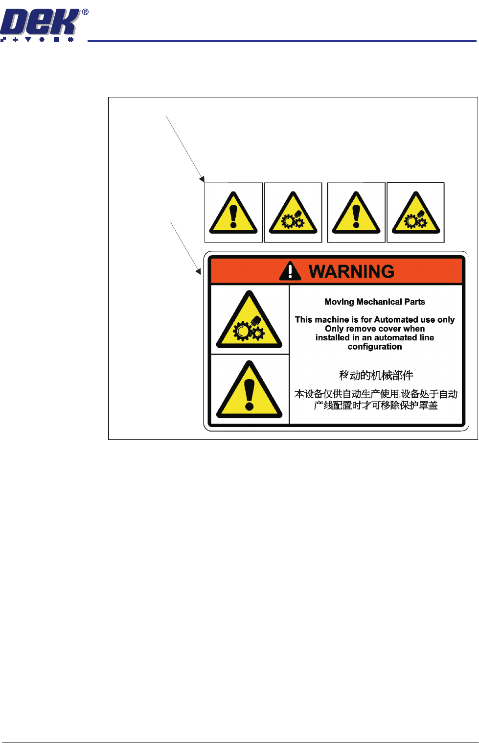
Warning Labels Check that the correct warning labels are attached to the appropriate areas of
all machines.
Situated behind the safety covers
Situated on the
safety covers