WaferTransportSolutionManual.pdf - 第11页
HEAVY PALLET RAILS OVERVIEW Chapter Issue 1 August 11 Wafer Transport Solutio n 1.3 Precision W afer Pallet Figure 1-3 Precisio n W afer Pallet Item Description Item Description 1 W afer Pallet Aligning Shim 7 Shim Groov…
HEAVY PALLET RAILS
OVERVIEW
1.2 Wafer Transport Solution Chapter Issue 1 August 11
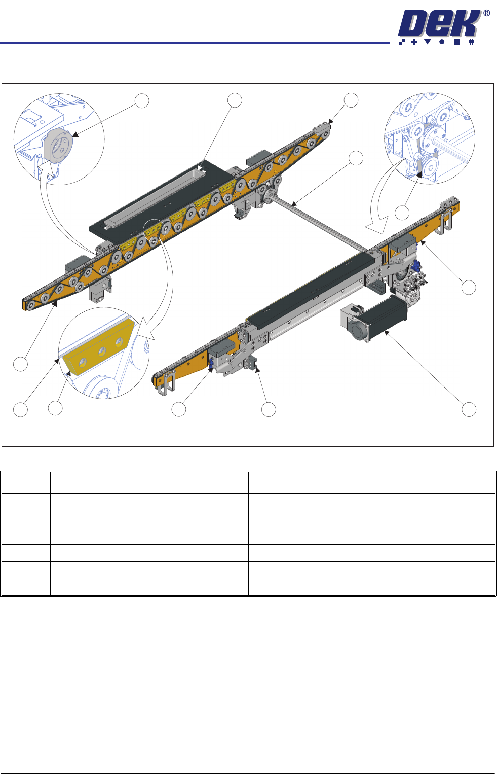
Heavy Pallet Rails
Figure 1-2 Heavy Pallet Rails
Item Description Item Description
1 Ball Placement Sphere Dump Tray 7 Linear Rail Clamp (2 Positions)
2 Safety Stop (2 Positions) 8 Beam Lift Cylinder (4 Positions)
3 Linked Transport Belt Drive Shaft 9 Pallet Support Blocks (10 Positions)
4 Transport Drive Belt 10 Pallet Snugger Rail
5 Transport Beam 11 Transport Belt
6 Transport Drive Motor 12 Rail Width Collar (2 Positions)
View on Front of Heavy Pallet Rails
1
2
3
6
5
7
8
4
10
12
11
9
HEAVY PALLET RAILS
OVERVIEW
Chapter Issue 1 August 11 Wafer Transport Solution 1.3
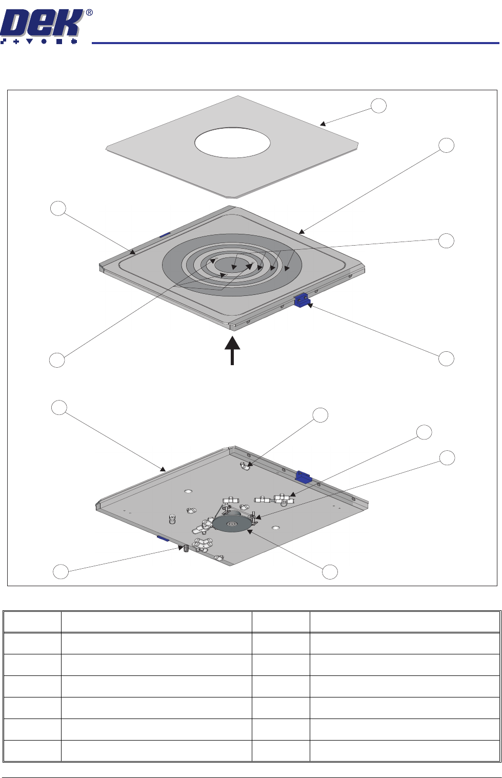
Precision Wafer Pallet
Figure 1-3 Precision Wafer Pallet
Item Description Item Description
1 Wafer Pallet Aligning Shim
7
Shim Groove Connector (2 Positions)
2 Wafer Pallet
8
Porous Segment Vacuum Connectors
3 Porous Vacuum Segments
9
Vacuum Pin (3 Positions)
4 Positioning Block (2 Positions)
10
Vacuum Pin Lift Mechanism
5 Wafer Release Pin Holes
11
Ground/Earth Point
6 Shim Vacuum Groove
12
Pallet Overhang Edge (2 Positions)
A
View from Top of Precision Wafer Pallet
View on A
1
2
4
3
5
6
8
9
10
11
12
7

HEAVY PALLET RAILS
OVERVIEW
1.4 Wafer Transport Solution Chapter Issue 1 August 11
Pallet Loading and Unloading
WARNING
HEAVY OBJECT. EXTREME CAUTION SHOULD BE EXERCISED WHEN
MANUALLY HANDLING HEAVY ITEMS INTO OR OUT OF THE MACHINE.
The precision wafer pallet has four porous concentric vacuum rings; an external
downline system’s vacuum system, secures the wafer and an aligning shim to
the pallet. Where small products are being processed the shim masks off the
outer porous rings. To release the wafer from the pallet, a mechanically driven
lift mechanism, attached to the pallet is used. An external downline system
provides the means to pick up the wafer and transfer it to the next-in-line
machine tool. The pallet is manually unloaded.
Sequence 1. The pallet and wafer enter the machine on the rail’s transport belts; the pallet
has overhanging edges which sit on the transport rails.
2. A non-contact board stop system positions the pallet beneath the screen.
3. Four beam lift cylinders, fitted to the transport beams, retract. The transport
belts drop depositing the pallet onto pallet support blocks.
4. The pallet snugger plate moves forward to hold the pallet in position.
5. Based on a fiducial scan performed by the camera, the machine aligns the
screen to the pallet.
6. The rising table lifts the rails, and pallet, to print height.
7. The print cycle commences.
8. Following the print operation, the rails and pallet lower with the rising table.
9. The pallet snugger rail moves back to release the pallet.
10. The beam lift cylinders extend to lift the pallet off the support blocks.
11. The transport belts carry the pallet and wafer back to the external downline
system.
12. The wafer holding vacuum switches off.
13. The vacuum release pin lift mechanism is actuated by the external handler
system.
14. The three pins on the lift mechanism rise through the pallet, raising the wafer
clear from the pallet and the shim.
15. The downline system removes the wafer and transports it to the next-in-line
tool; it can be manually removed.
16. The pallet remains in position with the pins up.
17. A wafer is placed on the pins.
18. Pin vacuum turns on.
19. The pins retract.
20. The wafer vacuum turns on in the wafer area; pin vacuum turns off.
21. Pallet moves into the DEK Printer.
The sequence repeats until all wafers have printed.