WaferTransportSolutionManual.pdf - 第13页
HEAVY PALLET RAILS MECHANICAL DETAIL Chapter Issue 1 August 11 Wafer Transport Solutio n 1.5 MECHANICAL DET AIL Rising T able T wo front table clamp s are fitted, they clamp the front rail to the rising table. This confi…

HEAVY PALLET RAILS
OVERVIEW
1.4 Wafer Transport Solution Chapter Issue 1 August 11
Pallet Loading and Unloading
WARNING
HEAVY OBJECT. EXTREME CAUTION SHOULD BE EXERCISED WHEN
MANUALLY HANDLING HEAVY ITEMS INTO OR OUT OF THE MACHINE.
The precision wafer pallet has four porous concentric vacuum rings; an external
downline system’s vacuum system, secures the wafer and an aligning shim to
the pallet. Where small products are being processed the shim masks off the
outer porous rings. To release the wafer from the pallet, a mechanically driven
lift mechanism, attached to the pallet is used. An external downline system
provides the means to pick up the wafer and transfer it to the next-in-line
machine tool. The pallet is manually unloaded.
Sequence 1. The pallet and wafer enter the machine on the rail’s transport belts; the pallet
has overhanging edges which sit on the transport rails.
2. A non-contact board stop system positions the pallet beneath the screen.
3. Four beam lift cylinders, fitted to the transport beams, retract. The transport
belts drop depositing the pallet onto pallet support blocks.
4. The pallet snugger plate moves forward to hold the pallet in position.
5. Based on a fiducial scan performed by the camera, the machine aligns the
screen to the pallet.
6. The rising table lifts the rails, and pallet, to print height.
7. The print cycle commences.
8. Following the print operation, the rails and pallet lower with the rising table.
9. The pallet snugger rail moves back to release the pallet.
10. The beam lift cylinders extend to lift the pallet off the support blocks.
11. The transport belts carry the pallet and wafer back to the external downline
system.
12. The wafer holding vacuum switches off.
13. The vacuum release pin lift mechanism is actuated by the external handler
system.
14. The three pins on the lift mechanism rise through the pallet, raising the wafer
clear from the pallet and the shim.
15. The downline system removes the wafer and transports it to the next-in-line
tool; it can be manually removed.
16. The pallet remains in position with the pins up.
17. A wafer is placed on the pins.
18. Pin vacuum turns on.
19. The pins retract.
20. The wafer vacuum turns on in the wafer area; pin vacuum turns off.
21. Pallet moves into the DEK Printer.
The sequence repeats until all wafers have printed.
HEAVY PALLET RAILS
MECHANICAL DETAIL
Chapter Issue 1 August 11 Wafer Transport Solution 1.5
MECHANICAL DETAIL
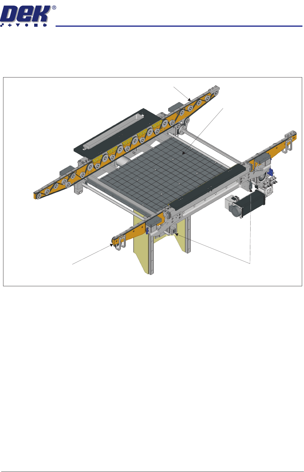
Rising Table Two front table clamps are fitted, they clamp the front rail to the rising table. This
configuration ensures that the rails and pallet are delivered to print height with
the rising table.
NOTE
Clatter bars, as used on a conventional system, are not used. Rail heights are
derived from the rising table position.
View of Rising Table with Heavy Pallet Rails Fitted
Heavy Pallet Rail - Front Transport Rail
Heavy Pallet Rail - Rear Transport Rail
Manual Tooling Plate
Front Rail Clamps
HEAVY PALLET RAILS
MECHANICAL DETAIL
1.6 Wafer Transport Solution Chapter Issue 1 August 11
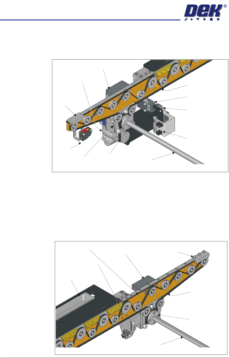
Transport Mechanism
Pallet Feed The Transfer Drive Motor drives the transfer belt via a 10:1 ratio gearbox which,
drives the transport belt shaft. This directly coupled arrangement, drives the
transport belts on the front and the rear rails synchronously.
A rail end sensor detects when the pallet is approaching the end of the rail,
should this occur motor control ceases and the pallet is stopped. Safety stops
are positioned on the rails at the opposite end to the pallet input. They are fitted
to each rail to physically prevent the pallet from running off the rail ends should
the user inadvertently change the transport rail direction.
Two transport beam lift cylinders are fitted to both sides of the front and rear
rails. They work together to drop the transport beams allowing the pallet to rest
on the pallet support blocks. At the end of the print operation the lift cylinders
lift, the belts are free to drive the pallet out of the printer to the downline
equipment.
Transport Belt
Right Side
Table Clamp
Data/Electrical
Connectors Housing
View on Rear of Front Transport Rail
Transport Belt
Drive Shaft
Transport Drive
Motor
Drive
Transfer Belt
Belt
Tensioner
Rail End
Sensor
Safety
Stop
Transport Drive
Gear Housing
Transport Beam
Lift Cylinder
View on Front of Rear Transport Rail
Transport Belt
Transport Belt
Drive Shaft
Transport Beam
Lift Cylinder
Safety
Stop
Rear Transport
Drive Belt Pulley
Transport Beam
Pallet Support Blocks
Sphere Dump Tray