WaferTransportSolutionManual.pdf - 第16页
HEAVY PALLET RAILS MECHANICAL DETAIL 1.8 Wafer Transport Solution Chapter Issue 1 August 11 Figure 1-4 Rais ed T ransport Beam Pall et Clearance Accomodating Pallets of Dif ferent Sizes The rear transport rail assembly c…

HEAVY PALLET RAILS
MECHANICAL DETAIL
Chapter Issue 1 August 11 Wafer Transport Solution 1.7
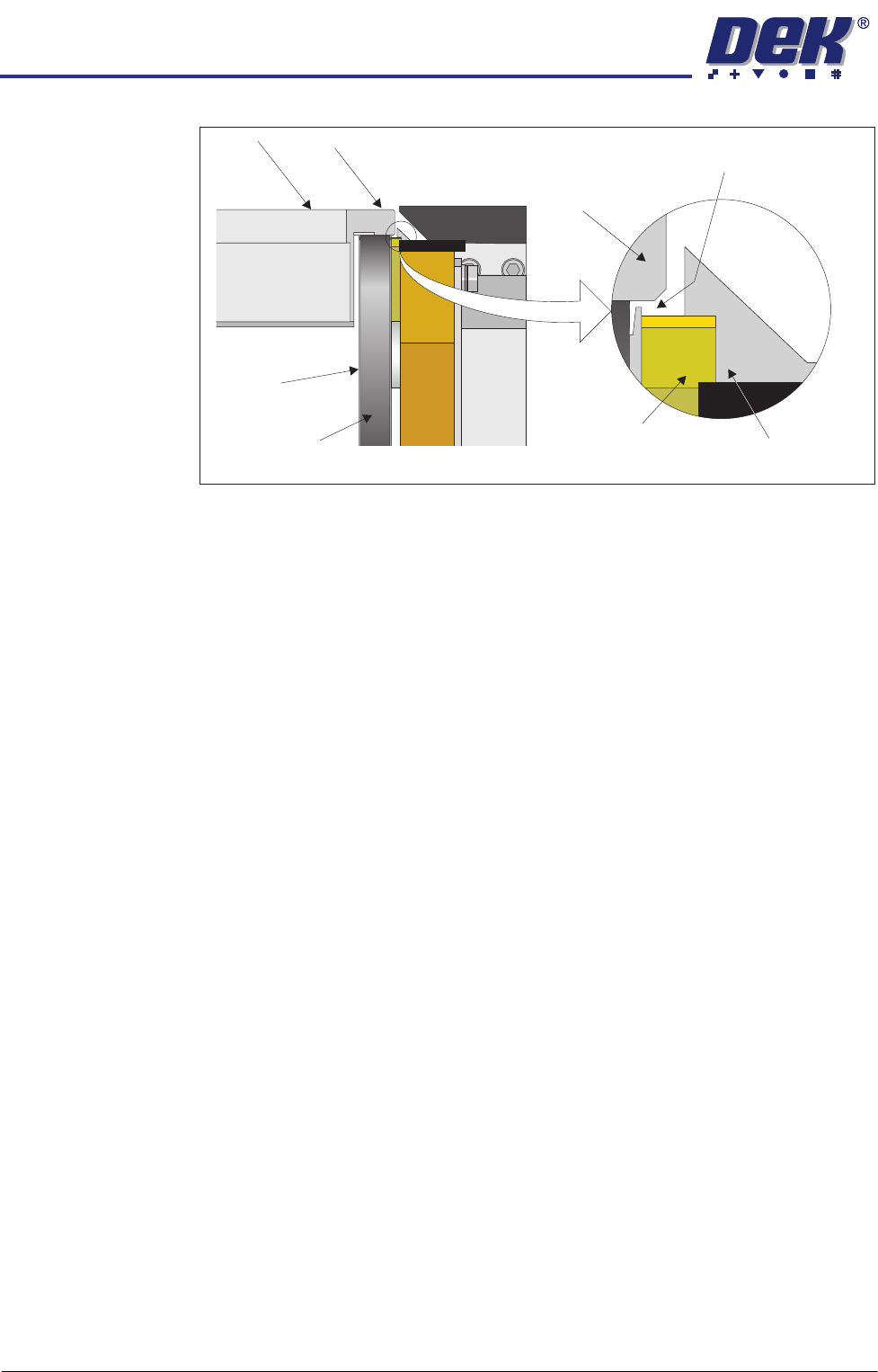
With the transport beams raised, the transport belts provide, nominally, 1mm of
clearance between the bottom edge of the pallet overhang and the pallet
support blocks. This clearance provides the pallet with an uninterrupted
passage as it moves along the length of the transport rails.
Pallet Transport
Pulley
Pallet Transport Belt
Below Transport Height
View on Rear of Front Transport Rail with Transport Beam Lowered
Pallet Transport
Belt
Pallet Transport Height
7mm
Pallet Transport
Pulley
Pallet Transport Belt
at Transport Height
Pallet Transport
Belt
~1mm above
~
View on Rear of Front Transport Rail with Transport Beam Raised
HEAVY PALLET RAILS
MECHANICAL DETAIL
1.8 Wafer Transport Solution Chapter Issue 1 August 11
Figure 1-4 Raised Transport Beam Pallet Clearance
Accomodating
Pallets of Different
Sizes
The rear transport rail assembly can be adjusted toward the front or rear of the
machine to accommodate pallets of different dimensions. As the front and rear
rail assemblies are permanently linked by the transport belt drive shaft the
transport belts always move simultaneously. For rail width adjustment see the
Adjustments and Settings section of this manual.
View on Left End of Front Transport Rail with Transport Beam Raised
Pallet
Pallet Overhang
Transport Belt
Transport
Pulley
Snugger Rail
Pallet Support
Block
1mm Gap Between Pallet
and Pallet Support Block
Pallet
HEAVY PALLET RAILS
MECHANICAL DETAIL
Chapter Issue 1 August 11 Wafer Transport Solution 1.9
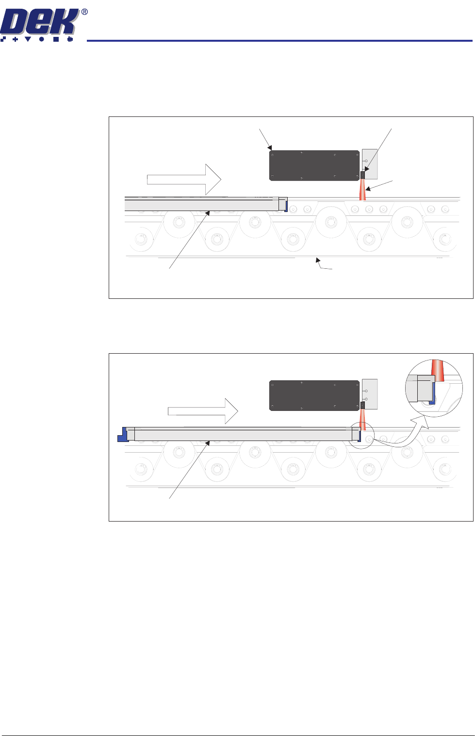
Non-contact Board
Stop System
The board stop consists of a sensor fitted to the camera. As the pallet moves
into the print station the sensor detects its position.
To maintain a fast core cycle rate for print operations, the pallet (and wafer)
enter the machine very quickly (500mm/s).
As soon as the front edge of the pallet is detected, by the board at stop sensor,
the transport belt drive mechanism reduces speed, slowing the speed of the
pallet.
The camera and sensor assembly quickly relocates to the final alignment
position. This position is between 62mm and 72mm from the original camera
and sensor position. The pallet continues to advance at the reduced rate,
allowing the camera to be in position ahead of the pallet’s arrival, increasing the
Camera Board at Stop
Sensor
Pallet Enters
at 500mm/s
Pallet
View on Front of Pallet on Wafer Transport Rail (Front Rail Not Shown)
Rear Transport Rail Mechanism
Sensor Beam
Pallet
View on Front of Pallet Breaking Sensor Beam (Front Rail Not Shown)
Pallet Enters
Sensor Beam