WaferTransportSolutionManual.pdf - 第22页
HEAVY PALLET RAILS MECHANICAL DETAIL 1.14 Wafer Transport Solutio n Chapter Issue 1 August 11 Leg Assemblies The four leg assemblies, each have a leaf spring, wh ich is atta ched to the rising table linear bearing clamp …
HEAVY PALLET RAILS
MECHANICAL DETAIL
Chapter Issue 1 August 11 Wafer Transport Solution 1.13
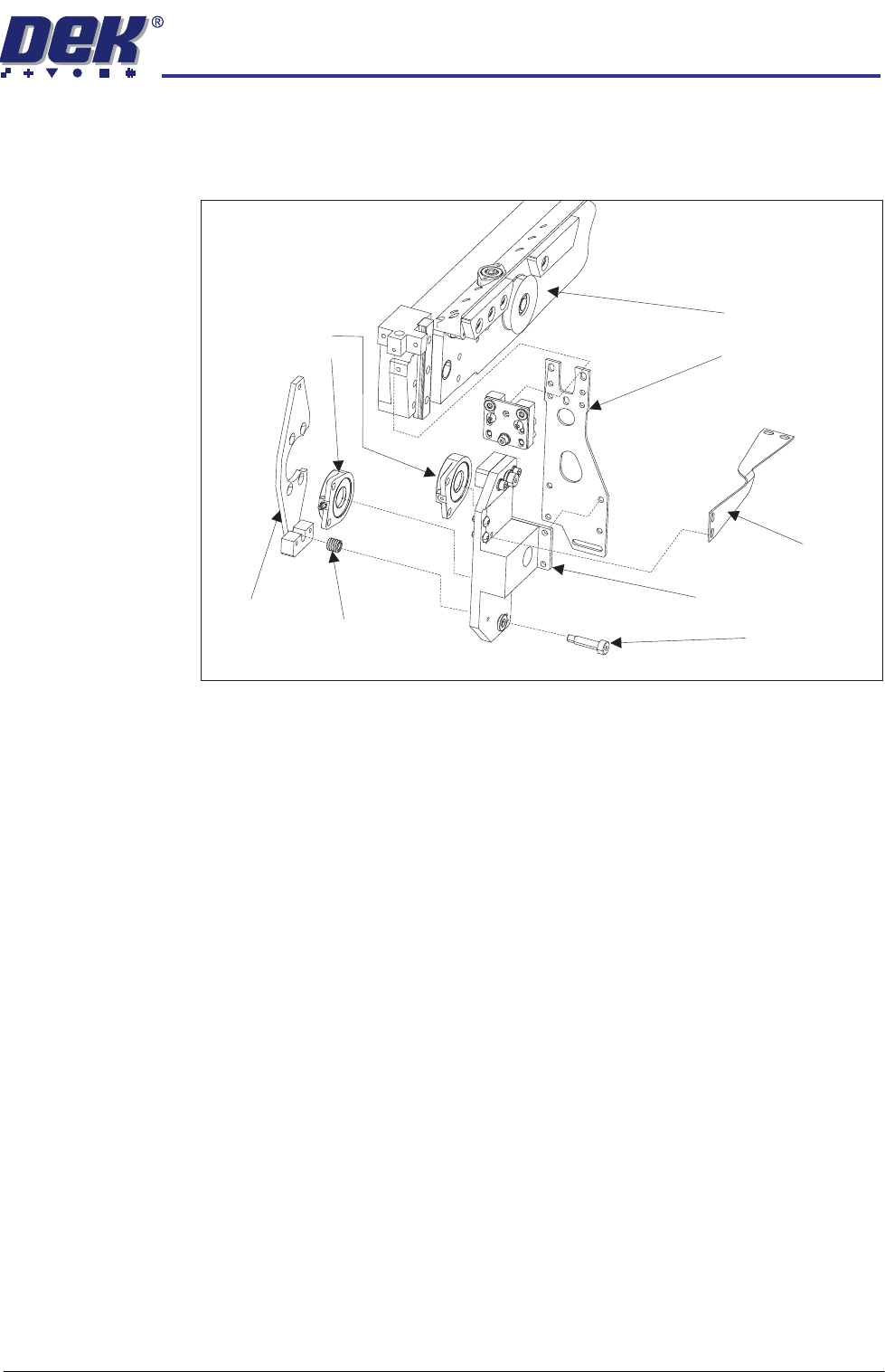
The pneumatically operated bellows act against a pair of fixed plates (only the
l.h.s shown in the diagram). The bellows are secured to the moveable bellows
mounting plates which are in-turn mounted to the snugger via a leg leaf spring
and a horizontal tie.
In operation, the left hand and the right hand bellows sets work together. They
move the snugger toward the front of the printer, clamping the pallet. The
system air pressure is applied causing all four bellows to expand, pushing the
snugger forward.
At the end of the print operation the pallet is released. Air pressure in each of
the bellows is exhausted, allowing the return spring assemblies to return the
moving plate back to the start location. The return spring assemblies are held
in place by a shoulder bolt which screws into the fixed plate.
Fixed Plate
Upper Bellows
Snugger
Lower Bellows
Bellows Mounting Plate
Leg Leaf Spring
Shoulder Bolt (2)
Return Spring (2)
Partially Exploded View (l.h.s. bellows) of the Snugger Mechanism
Horizontal Tie
HEAVY PALLET RAILS
MECHANICAL DETAIL
1.14 Wafer Transport Solution Chapter Issue 1 August 11
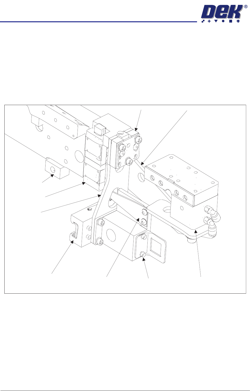
Leg Assemblies The four leg assemblies, each have a leaf spring, which is attached to the rising
table linear bearing clamps at the bottom end, and to the rail clamps at the top
end. On its own, the construction is flexible, however the rail beam is braced,
on the left hand side only, by an horizontal tie strap which locks it to the support
block.
The top of the beam lift cylinder attaches to the transport beam, the lift cylinder
pin pushes against the lift cylinder arm, creating the required lift. The beam
rises on the beam lift bearing during pallet transportation and retracts to position
the pallet for printing.
Lift Cylinder Arm
Beam Lift Cylinder
Rail Clamp
Rising Table Linear Bearing Clamp Tie Strap Support Block
View on Left Hand End of the Front Rail
Leg Leaf Spring
Beam Lift Bearing
Y Adjuster Block
HEAVY PALLET RAILS
ELECTRICAL SCHEMATIC
Chapter Issue 1 August 11 Wafer Transport Solution 1.15
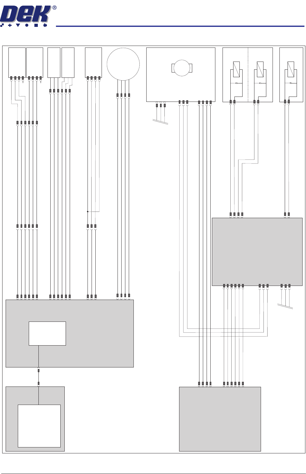
ELECTRICAL SCHEMATIC
Motherboard
USB
Machine
Controller M36
NextMove
ES
Machine PC
Power Supply
Enclosure M37
M36SK21
3SK35
M36SK28
+12V
DC IN 10
0V
+12V
DC IN 11
0V
Board at Left
Optical Sensor
Board at Right
Optical Sensor
8SK10
8SK03
M36SK11
+12V
DC IN 8
0V
+12V
DC IN 9
0V
Board at Stop
Optical Sensor
Board Stop
S/State Switch
10SK24
+V
Out
0V
(L)
M36SK19
+12V
DC IN 5
0V
8SK26
Moving
Rail Home
RE
BU
OG
YE
Moving Rail
Stepper Motor
Heavy Pallet
Servo Motor
Node 17
M
CAN_H
CAN_L
CAN_GND
CAN_H
CAN_L
CAN_GND
+42V SW
0V RETURN
+24V US
0V RETURN
Pneumatic Solenoid Bank
Snugger
Belts Drop
Phase A-
Phase A+
Phase B+
Phase B-
N17SK4
N17SK3
N17SK2
8SK20
M37SK20
+42V SW
0V RETURN
+24V US
0V RETURN
M37SK04
+24V US
0V RETURN
+24V SW
0V RETURN
+12V
0V RETURN
N2SK1
+24V US
0V RETURN
+24V SW
0V RETURN
+12V
0V RETURN
Machine Node 2
CAN_H
CAN_L
CAN_GND
CAN_H
CAN_L
CAN_GND
N2SK3
N2SK2
CAN Bus Out
To Node 4
CAN Bus In
From Node 7
N2SK4
DIG OUT 9 (24V US)
0V RETURN
DIG OUT 15 (24V US)
0V RETURN
16SK10
16SK03
M36SK22
8SK34
DIG OUT 9 (24V US)
0V RETURN
Vacuum Tooling
N2SK2
8SE8
8SE9
8SE06