WaferTransportSolutionManual.pdf - 第26页
HEAVY PALLET RAILS ADJUSTMENTS & SETTINGS 1.18 Wafer Transport Solutio n Chapter Issue 1 August 11 ADJUSTMENTS & SETTINGS NOTE Before commencing the procedures in this section, ensure that the too ling area is cl…
HEAVY PALLET RAILS
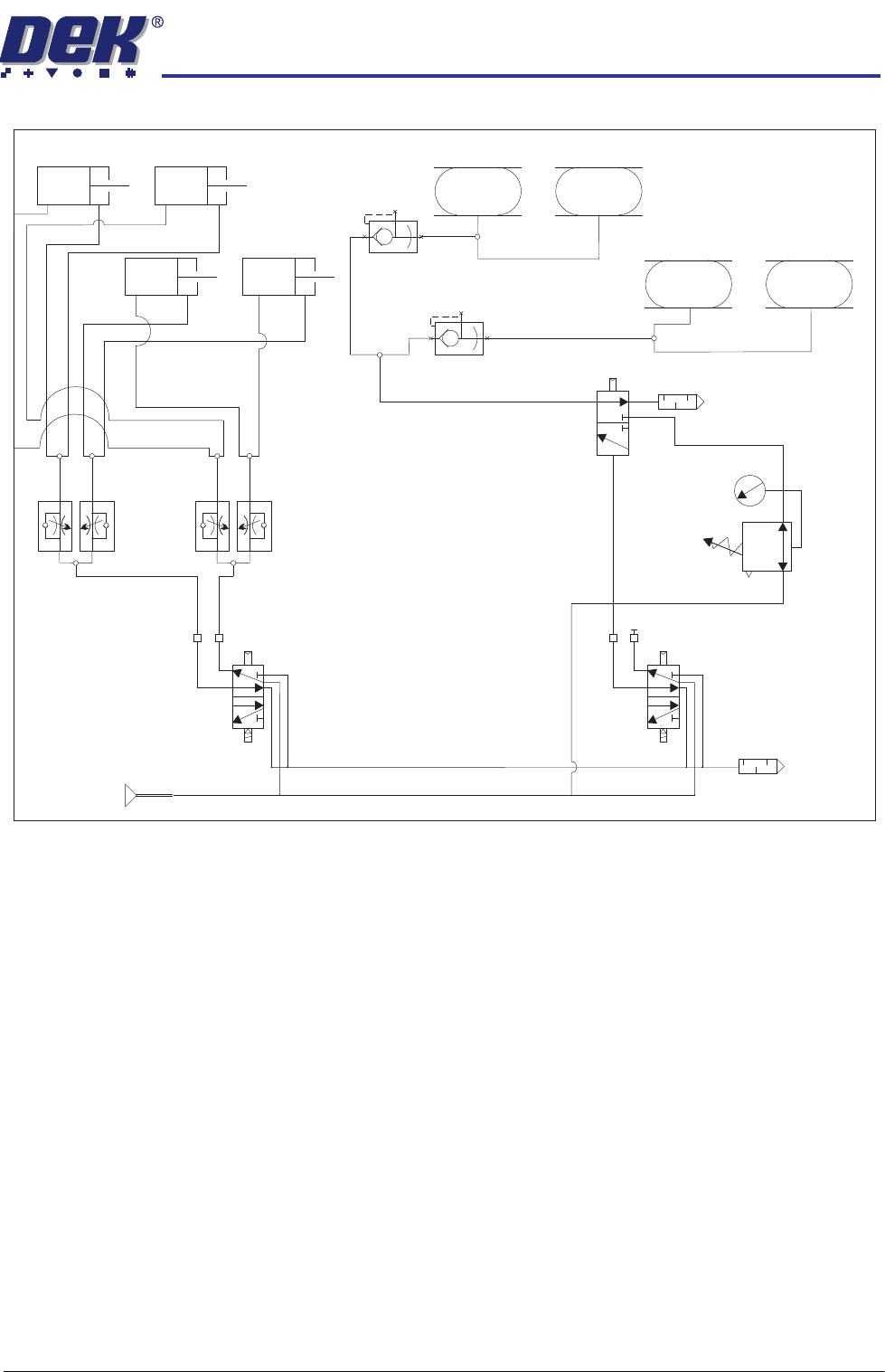
PNEUMATIC SCHEMATIC
Chapter Issue 1 August 11 Wafer Transport Solution 1.17
PNEUMATIC SCHEMATIC
Snugger Left
Snugger Right
IN
OUT
5/2
16SK10
5/2
16SK03
Flow Controllers
Snugger Pilot Valves
and Regulators
Rail Lift and Drop Cylinders
Mains Air In
A
B
A
B
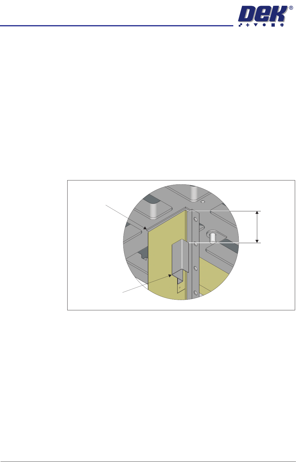
HEAVY PALLET RAILS
ADJUSTMENTS & SETTINGS
1.18 Wafer Transport Solution Chapter Issue 1 August 11
ADJUSTMENTS & SETTINGS
NOTE
Before commencing the procedures in this section, ensure that the tooling area
is clear of all tools, and the table surface is clean.
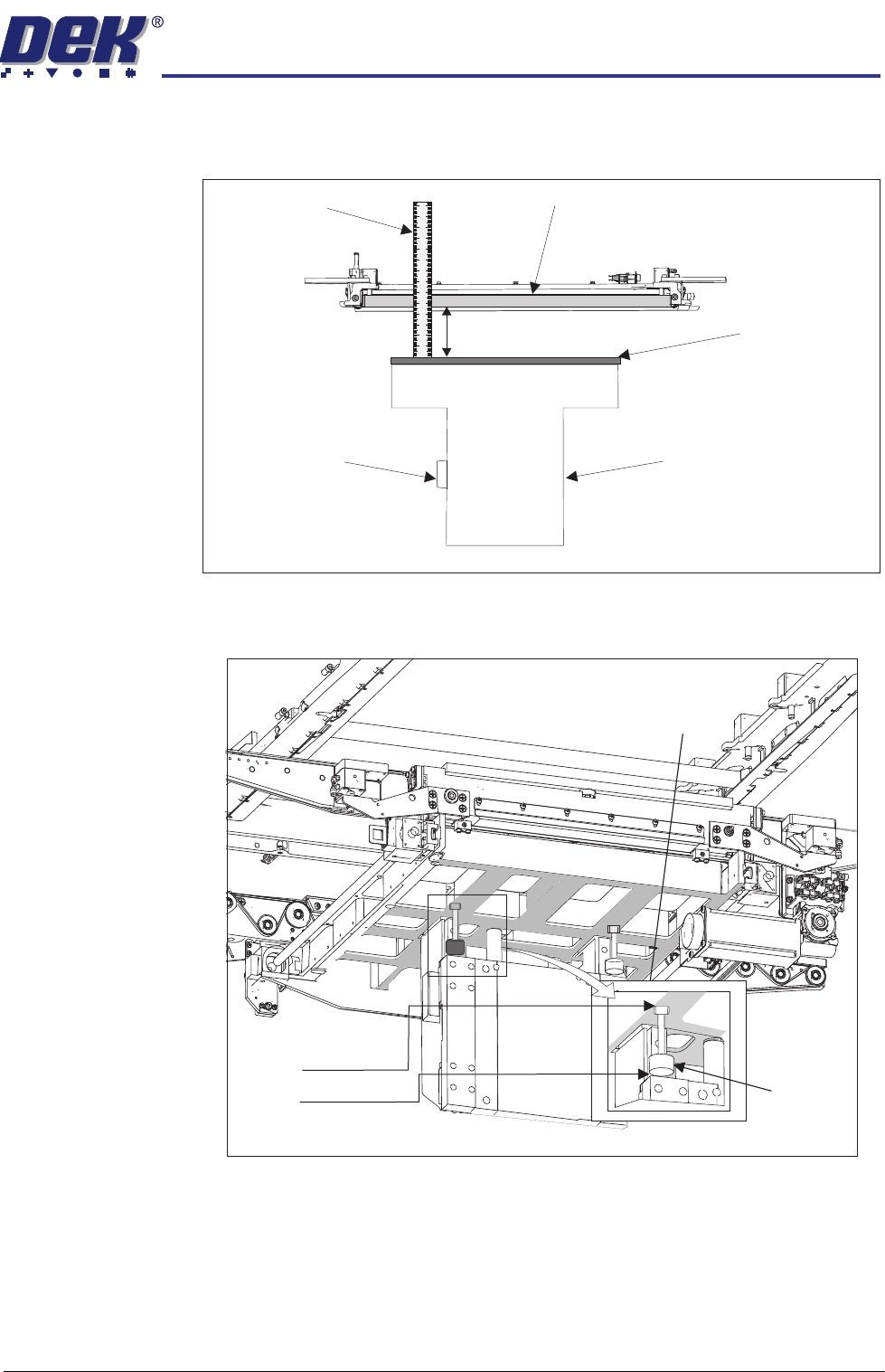
Rising Table Home
Vane
To adjust the rising table home vane, carry out the following:
1. On the machine interface select Maintenance.
2. Select Diagnostics.
3. Select the Rising Table.
4. Select Home Rising Table.
5. Make provision to access the printer on the left hand side.
6. Remove the lower cover from the left side of the printer.
7. Locate the rising table home vane on the rising table left leg.
8. Measure a 122mm gap between the top of the vane and the step on the
underside of the rising table.
9. If adjustment is required, slacken the home vane retaining screws and adjust
the vane.
NOTE
Ensure the vane does not foul the rising table home sensor.
10. Using a combination of the Next and Previous buttons alternately select
Rising Table To Transport Height and Home Rising Table.
11. Observe that the home vane enters the sensor and does not foul. Adjust
the vane as required to prevent this from happening.
12. Insert the Setting Bar (201121) into the ‘C’ Chase.
13. Select Home Rising Table.
View on Underside of Rising Table
122mm
Home Vane
Step
HEAVY PALLET RAILS
ADJUSTMENTS & SETTINGS
Chapter Issue 1 August 11 Wafer Transport Solution 1.19
14. Using a steel rule measure the distance between the top of the table (tooling
plate) and the bottom of the setting bar. The measurement achieved should
be: 188mm +/_1.0mm.
Table Buffer
Settings
The table buffers are set to 91mm from the underside of the table casting to the
base of the buffer. Adjustment is made by slackening off the top locknut and
screwing the stud in the required direction to give 91mm overall length.
View on Front of Machine
Steel Rule
Home Vane
Rising Table
Setting Bar in the Chase
Tooling Plate
188mm +/- 1.0mm
91mm
Locknut
Buffer
View from Under the Rising Table