WaferTransportSolutionManual.pdf - 第30页
HEAVY PALLET RAILS ADJUSTMENTS & SETTINGS 1.22 Wafer Transport Solutio n Chapter Issue 1 August 11 14. Release the four left hand bearing mount grubscrews. 15. Loosen the right-hand adjuster block locking gru bscrew …
HEAVY PALLET RAILS
ADJUSTMENTS & SETTINGS
Chapter Issue 1 August 11 Wafer Transport Solution 1.21
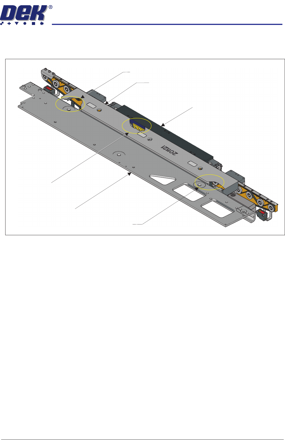
8. Place two tooling pins behind the front rail as shown below.
9. Ensure that the camera is parked at the far left location of the camera beam.
10. Sit the setting bar (201121) on the tooling pins and the rail support blocks.
11. Pull the camera beam toward the setting bar until it just touches the bar.
12. Press the System button.
13. Select Toggle Heavy Rail Drop. This action lowers the setting bar onto
the front rail support blocks; the belts are lowered out of the way.
Cut-away showing a tooling pin
used to support the setting bar
Cut-away showing a rail support block
used to support the setting bar
Cut-away showing a tooling pin
used to support the setting bar
Front Rail
Setting Bar
Camera Beam
HEAVY PALLET RAILS
ADJUSTMENTS & SETTINGS
1.22 Wafer Transport Solution Chapter Issue 1 August 11
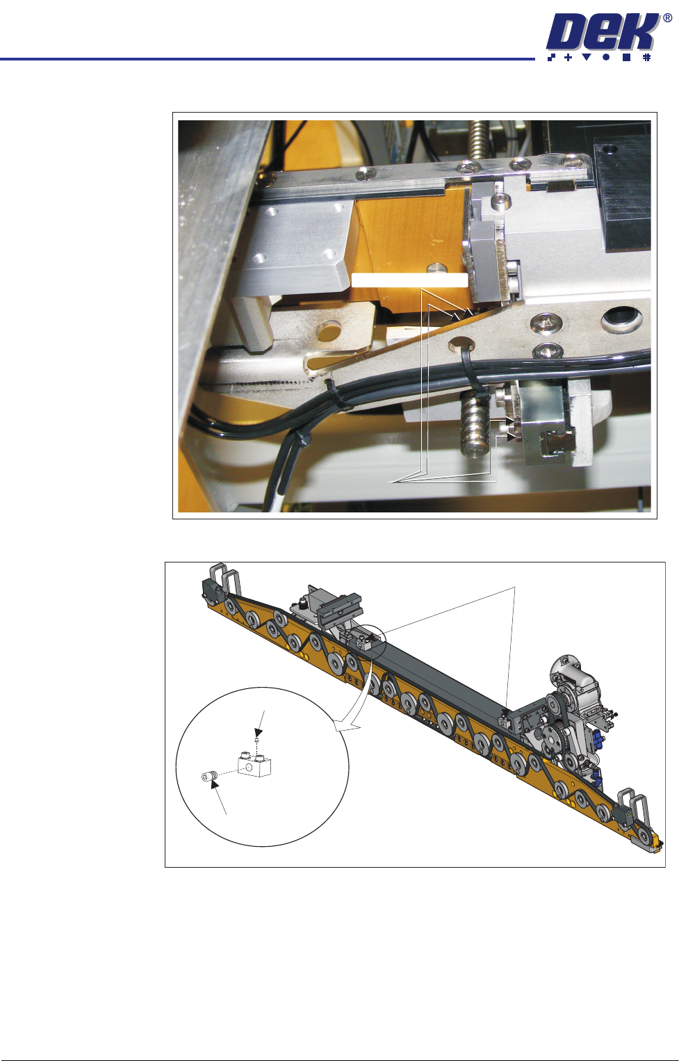
14. Release the four left hand bearing mount grubscrews.
15. Loosen the right-hand adjuster block locking grubscrew.
Grubscrews
Grubscrews (at rear)
View on Underside of the Front Rail
Adjuster Blocks
Locking
Grubscrew
Adjustment
Screw
HEAVY PALLET RAILS
ADJUSTMENTS & SETTINGS
Chapter Issue 1 August 11 Wafer Transport Solution 1.23
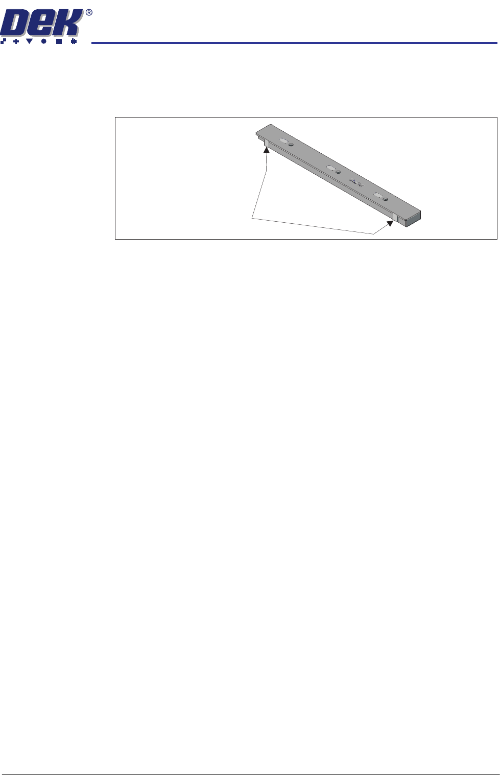
16. Using the adjustment screw, pivot the beam about the left hand side until the
setting bar is parallel to the camera; measured at the two setting bar test
faces as shown below. Use an 0.05mm feeler gauge to test the alignment
of the rail to the camera beam.
17. If the adjuster block needs to be adjusted, release the locking grubscrew
and unscrew the adjustment screw. Lock the correct position: 44mm, with
the locking grubscrew.
18. Lock the adjustment block locking grubscrews.
19. Recheck the rail parallelism.
20. Move the camera beam to the centre; remove the setting bar and tooling
pins.
21. Close the front printhead cover.
22. Press the System button.
23. Select Exit.
24. Select Back.
25. Ensure that the side panel is refitted to the machine and move the machine
back into line.
Setting Bar Test Faces