WaferTransportSolutionManual.pdf - 第33页
HEAVY PALLET RAILS ADJUST MENTS & SE TTINGS Chapter Issue 1 August 11 Wafer Transport Solutio n 1.25 13. Close the front printhead cover . 14. Press the System button. Rail Guide Alignment T o set up and align the ra…
HEAVY PALLET RAILS
ADJUSTMENTS & SETTINGS
1.24 Wafer Transport Solution Chapter Issue 1 August 11
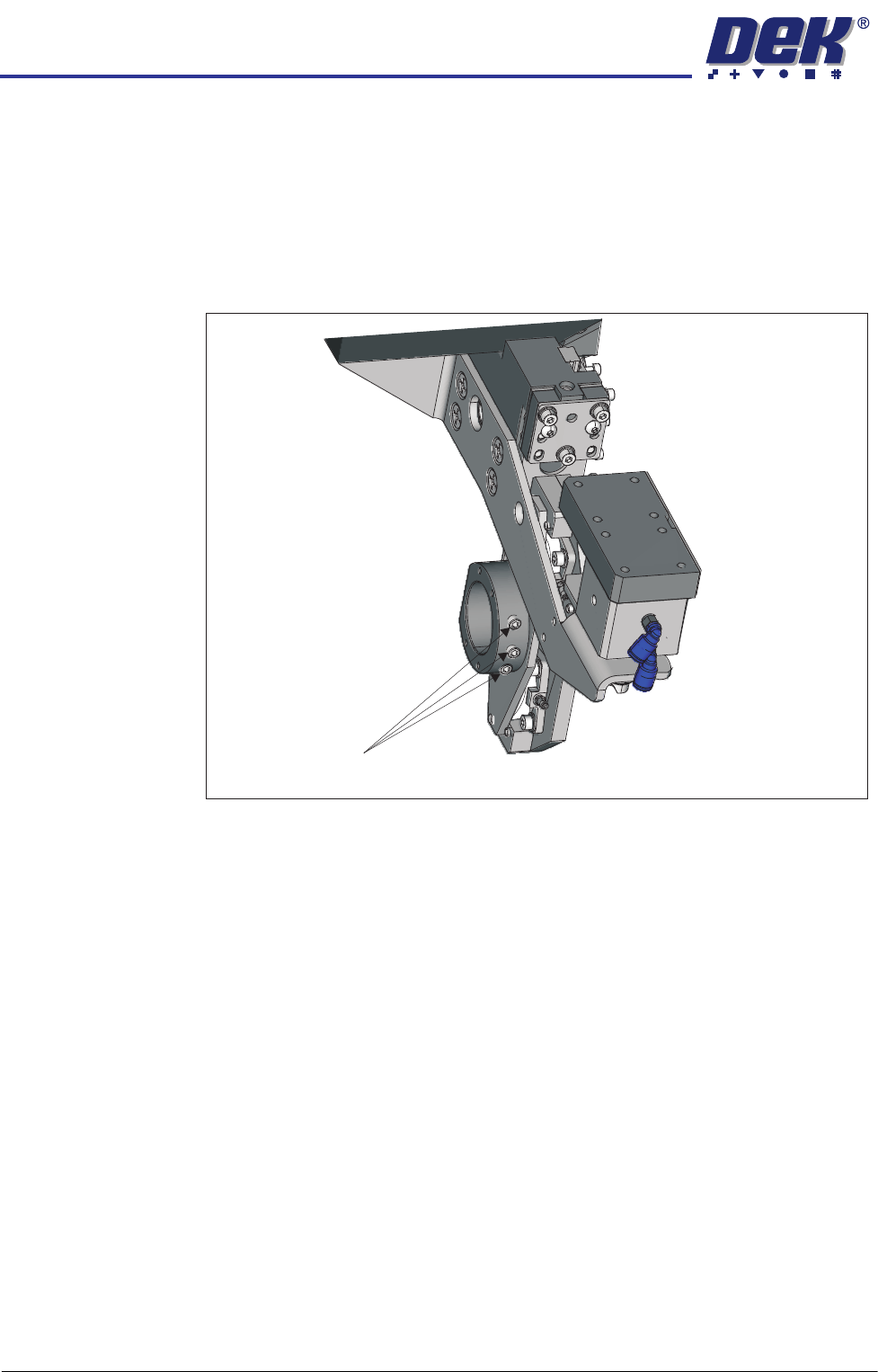
Rear Rail Alignment 1. On the user interface navigate to the Diagnostics page.
2. Select Rail System.
3. Drive the rail to 250mm.
4. Open the front printhead cover.
5. Loosen the three grubscrews retaining the left and right hand rail width
leadscrew nuts.
6. Using a digital vernier, measure between the rails at both ends of the
snugger rail. Adjust the rail parallelism by rotating the leadscrew nuts to
achieve parallelism of 0.05mm.
Board Width Check 1. Check the rail width, in three places along the rail length, with the digital
vernier; it should be within the limits 250.15mm to 250.25mm.
2. If the readings are outside the stated tolerance above, on the user interface
select Diagnostics.
3. Select Rail System.
4. Select Set Rail Board Width Calibration.
5. Select Run Diagnost..
6. Select Incr. or Decr. to adjust the rail width to within the stated tolerance.
7. Select Move.
8. Recheck the dimension. If OK select Set, select Yes.
9. Select Home Rail Width.
10. Select Run.
11. Select Drive Rail to Board Width.
12. Recheck the board width tolerance.
Grubscrews
View on Left Hand End of the Rear Rail
HEAVY PALLET RAILS
ADJUSTMENTS & SETTINGS
Chapter Issue 1 August 11 Wafer Transport Solution 1.25
13. Close the front printhead cover.
14. Press the System button.
Rail Guide
Alignment
To set up and align the rail guides complete the following:
1. Select Setup Product.
2. Select Board Width.
3. Set the board width parameter to 75mm.
4. Select Accept.
5. Select Back.
6. Select Maintenance.
7. Select Diagnostics.
8. Select Rail System module.
9. Select Home Rail Width.
10. Select Drive Rail To Board Width.
11. Press the E-Stop.
12. Open the front printhead cover.
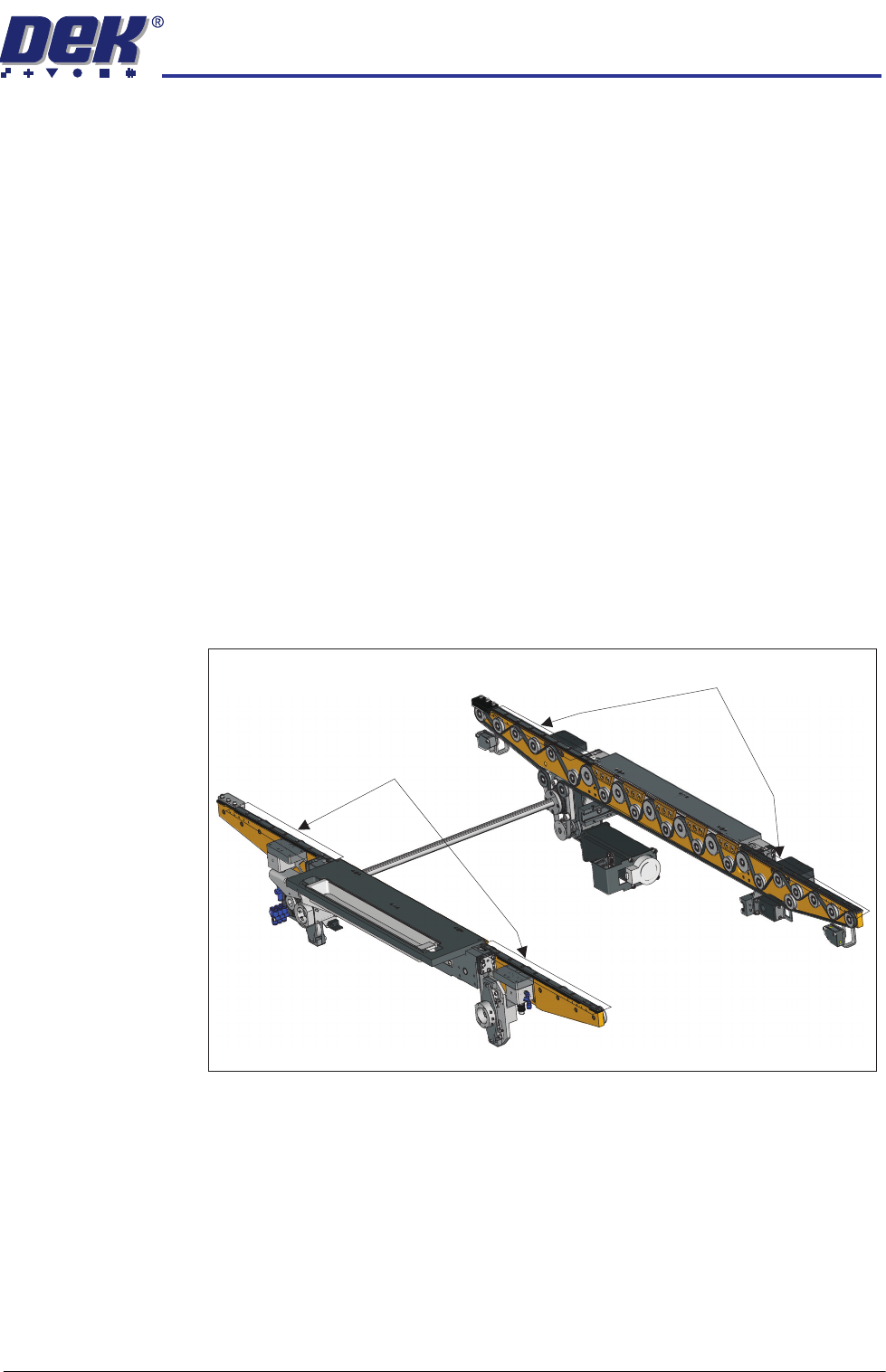
13. Loosen all the countersunk screws on each of the front and rear rail guides.
14. Place the setting bar (201121) upside down on the left hand side of the rails.
15. Wind the rear rail in by hand (rotate the rail width leadscrew) to contact the
setting bar. The setting bar sits on the front and rear transport belts.
16. There is a plastic strip guide beneath each clamping plate, ensure that the
plastic strips align against the setting bar.
17. Tighten all the countersunk screws.
18. Remove the setting bar.
19. Place the setting bar on the right hand side of the rails.
20. Slacken off the three M4 cap screws holding the safety stops on each rail.
Rear Rail Guide Countersunk Screws
Front Rail Guide Countersunk Screws

HEAVY PALLET RAILS
ADJUSTMENTS & SETTINGS
1.26 Wafer Transport Solution Chapter Issue 1 August 11
NOTE
For a right to right feed printer, the safety stops are located on the left
hand side.
21. Repeat the procedure for the right side rails.
22. Remove the setting bar.
23. Tighten the three M4 cap screws holding the safety stops on each rail.
24. Close the printhead front cover.
25. Release the E Stop.
26. Reactivate the system.