WaferTransportSolutionManual.pdf - 第38页
HEAVY PALLET RAILS ADJUSTMENTS & SETTINGS 1.30 Wafer Transport Solutio n Chapter Issue 1 August 11 NOTE All setting bars are marked with unique readings expressing the bar ’s flatness. The centre reading is always ze…
HEAVY PALLET RAILS
ADJUSTMENTS & SETTINGS
Chapter Issue 1 August 11 Wafer Transport Solution 1.29
keep the clamp fixings in contact with the beam ends.
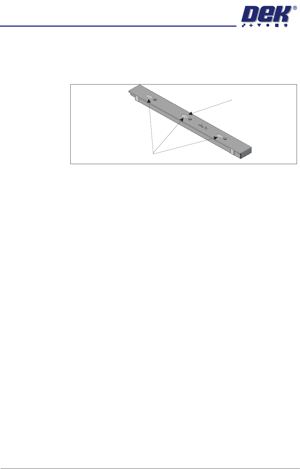
15. Place a tooling pin in the centre of the tooling table.
16. Align setting bar (201121) in the chase, with its centre hole over the tooling
pin.
17. Insert the depth micrometer into the centre hole of the setting bar touching
the tooling pin top.
18. Note the reading of the depth micrometer to the tooling pin.
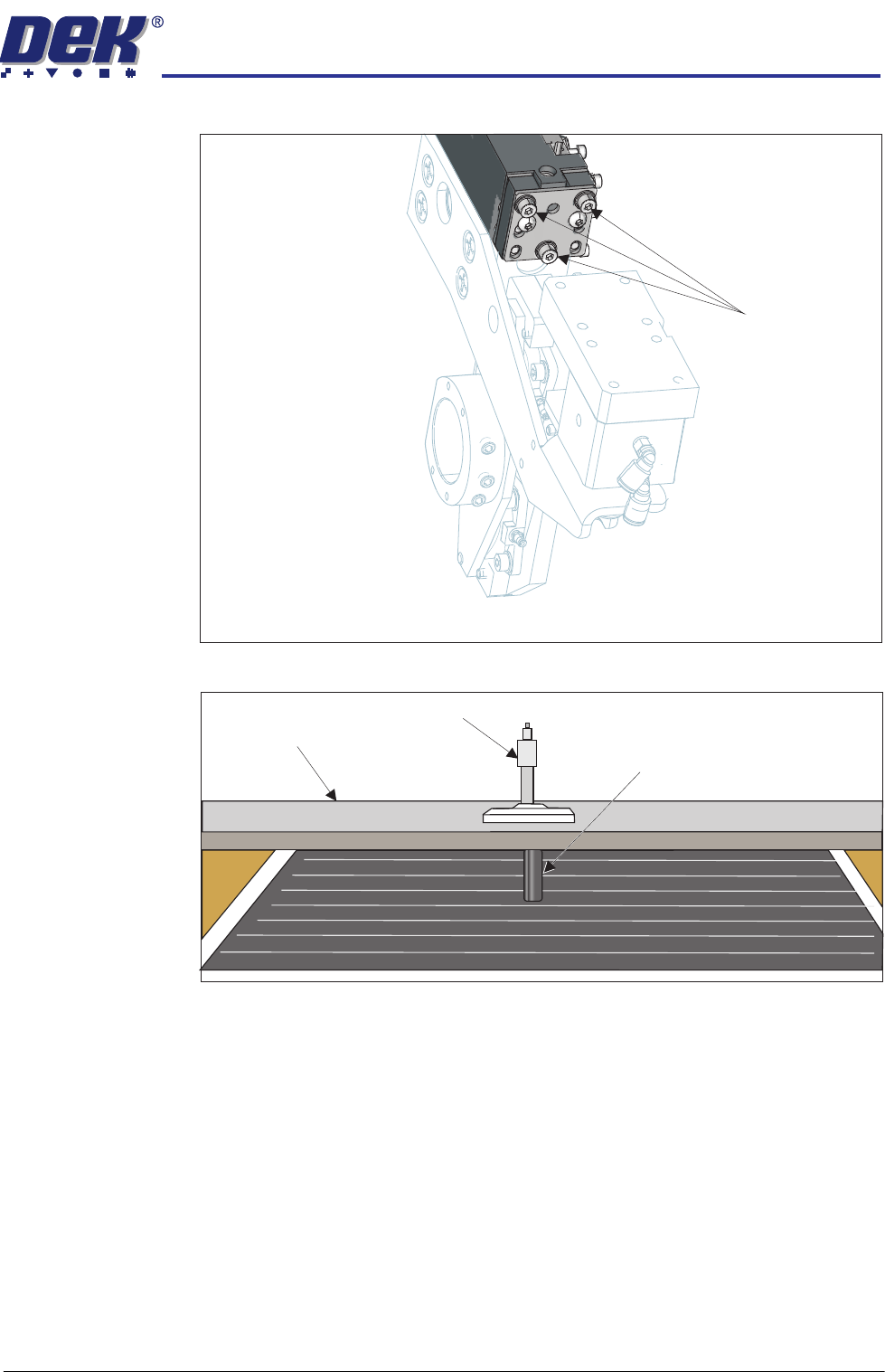
Locking Screws
View on Left Hand End of the Rear Rail
Setting Bar
Depth Micrometer
Tooling Pin
HEAVY PALLET RAILS
ADJUSTMENTS & SETTINGS
1.30 Wafer Transport Solution Chapter Issue 1 August 11
NOTE
All setting bars are marked with unique readings expressing the bar’s
flatness. The centre reading is always zero, the other readings are relative
to the centre. These markings are known as the setting bar flatness
calibration figures.
19. Remove the depth micrometer.
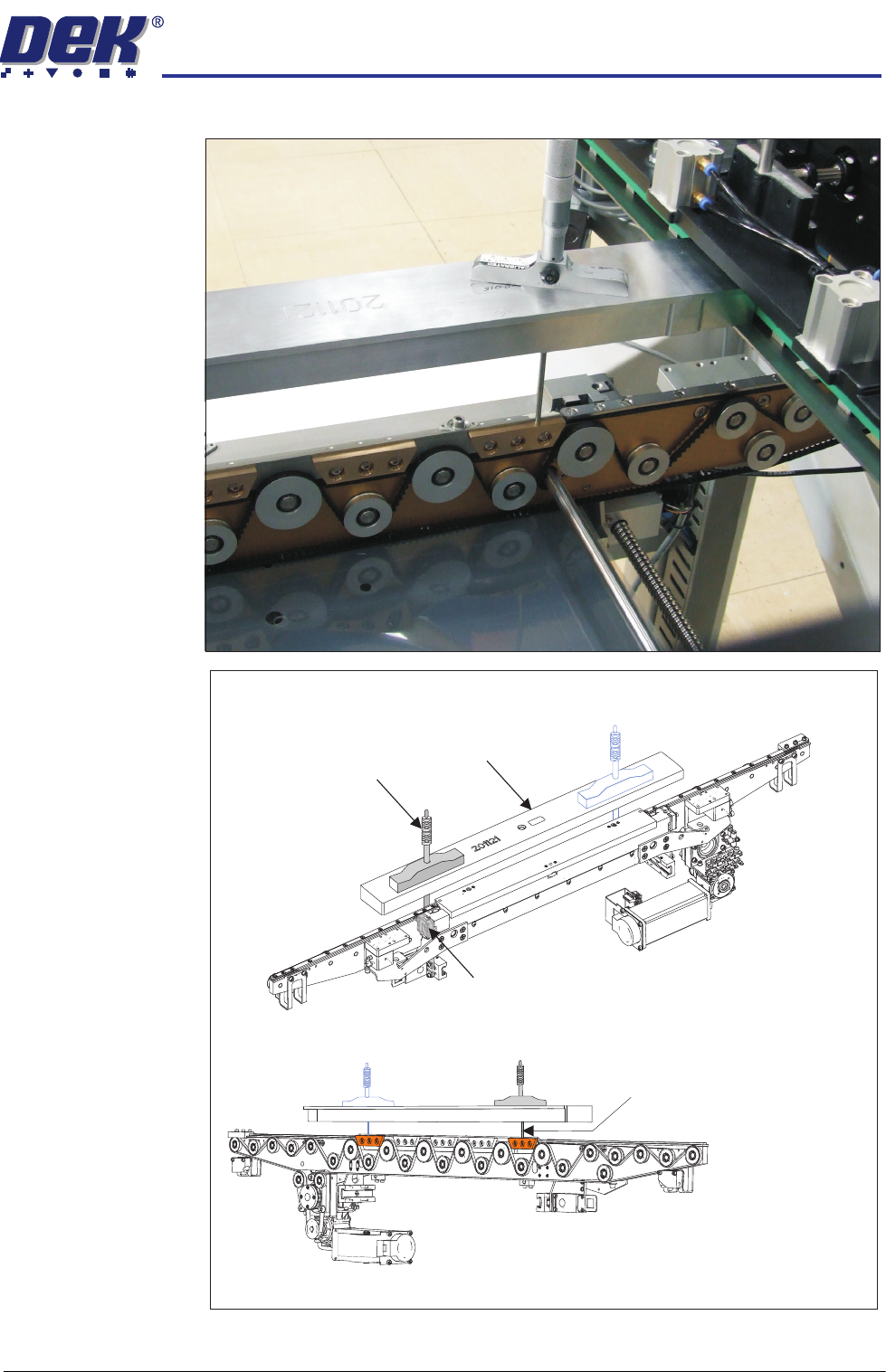
20. Move the setting bar forward in the chase, so that it is over the front beam
pallet support blocks.
21. Insert the depth micrometer into the left hole of the setting bar. The depth
Setting Bar Flatness Calibration Figures
Centre is Zero (0.00)
HEAVY PALLET RAILS
ADJUSTMENTS & SETTINGS
Chapter Issue 1 August 11 Wafer Transport Solution 1.31
micrometer tip contacts the left hand pallet support block.
View on Front Left Quarter of the Front Rail
View on the Rear of the Front Rail
Depth Micrometer
Depth Micrometer
(Location 2)
Rail Height Adjuster
Setting Bar
Micrometer readings taken
from the top surface of the
pallet support blocks as shown