WaferTransportSolutionManual.pdf - 第41页
HEAVY PALLET RAILS ADJUST MENTS & SE TTINGS Chapter Issue 1 August 11 Wafer Transport Solutio n 1.33 43. Using Decr . or Incr . . 44. Select the Rising T able . 45. Select Home Rising T able . Run the diagnostic. 46.…
HEAVY PALLET RAILS
ADJUSTMENTS & SETTINGS
1.32 Wafer Transport Solution Chapter Issue 1 August 11
22. Slacken off the rail height adjuster lock screws on both sides of the rail.
23. Adjust the set screws to raise or lower the rail, until the reading on the depth
micrometer is the same as that of the reading made with the depth microm-
eter on the tooling pin, ± the setting bar calibration figure. The difference
should be within ± 0.01mm.
24. Repeat the steps above (17 through 23) with the depth micrometer on the
right hand side.
25. Tighten all lock screws and confirm the setting.
26. Carry out the procedure for the rear rail.
27. Restore the E Stop.
28. Close the front printhead cover.
29. Press the System Button.
30. Select Exit.
31. Select Rail System.
32. Select Select Module.
33. Select Toggle Heavy Rail Drop. This holds the pallet in the correct location
without clamping and lowers the belts.
34. Open the printhead front cover.
35. Place the setting bar across the top of both rails front to back.
36. Using the depth micrometer through the setting bar, as previously described,
check all four corners of the pallet. The reading on the depth micrometer is
the same as that of the reading made with the depth micrometer on the
tooling pin, ± the setting bar calibration figure. The difference should be
within ± 0.01mm.
37. If required, adjust the rail height, and recheck the settings.
38. Remove all tooling.
39. Remove the two setting rods.
40. Close the front printhead cover.
41. Press the System button.
42. Select Exit.
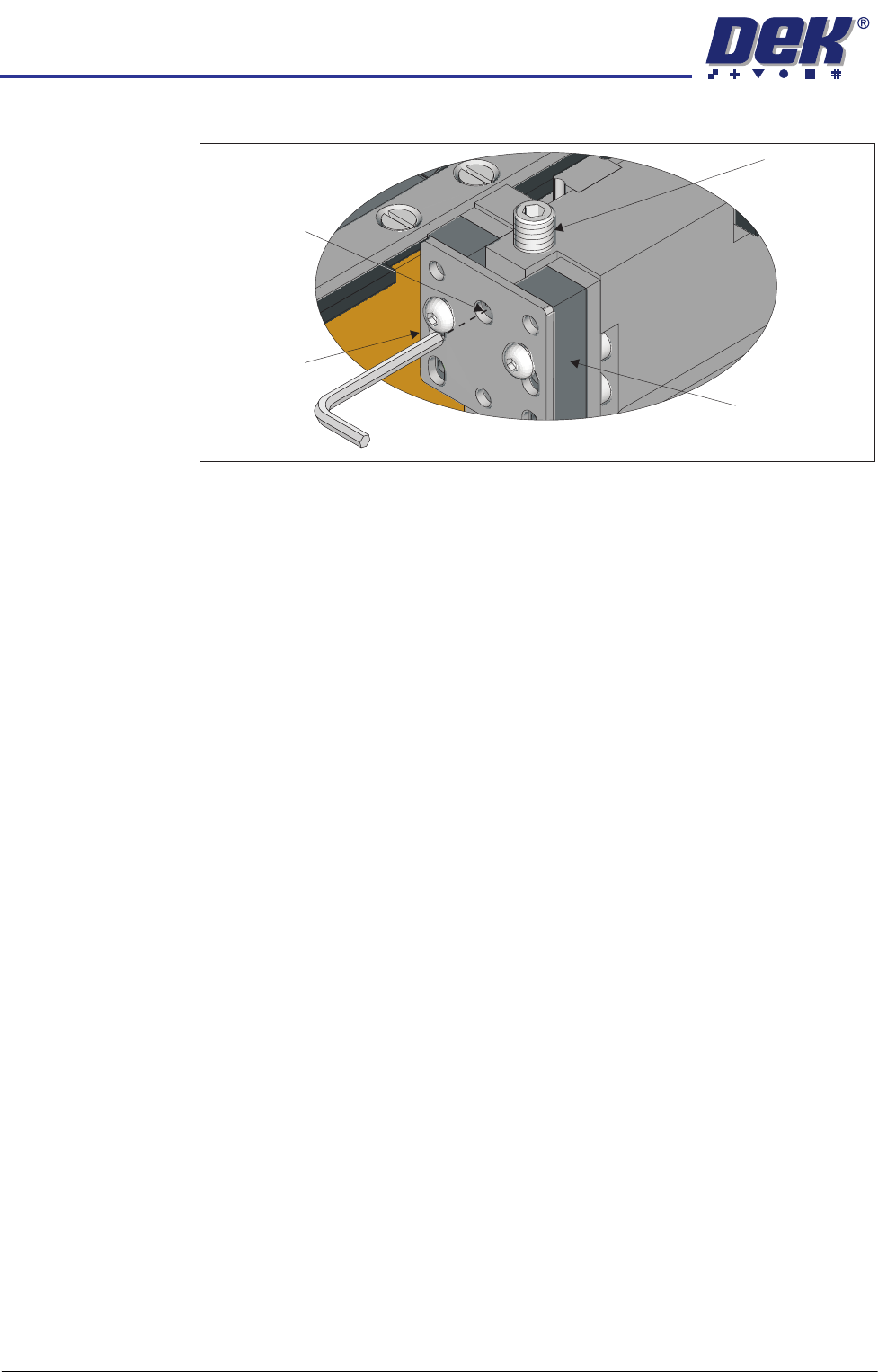
View on Left Front Rail Clamp
Set Screw
Rail Clamp
Linear Bearing
Height Adjuster
Lock Screw

HEAVY PALLET RAILS
ADJUSTMENTS & SETTINGS
Chapter Issue 1 August 11 Wafer Transport Solution 1.33
43. Using Decr. or Incr..
44. Select the Rising Table.
45. Select Home Rising Table. Run the diagnostic.
46. Open the printhead front cover.
Top Plate Adjustment
WARNING
HEAVY OBJECT. EXTREME CAUTION SHOULD BE EXERCISED WHEN
MANUALLY HANDLING HEAVY ITEMS INTO OR OUT OF THE MACHINE.
NOTE
The precision pallet, shim, rail top plates and setting bar are all manufactured
to a high degree of flatness and are susceptible to surface flaws that can
degrade their function. In the following procedure hard tooling is used in contact
with these surfaces which may cause markings or more significant damage, if
not handled carefully. Tooling used must be clean and blemish free. All effort
must be made to avoid dragging, dropping or knocking tools on the exposed
surfaces.
HEAVY PALLET RAILS
ADJUSTMENTS & SETTINGS
1.34 Wafer Transport Solution Chapter Issue 1 August 11
1. Ensure that the screen has been removed from the printer.
2. Ensure that the pallet and shim have been removed from the printer.
3. Select Setup Product.
4. Select Board Length Board Width.
5. Select Board Width. Set the board width to match the pallet.
6. Select Board Length. Set the board length to match the pallet.
7. Select Accept.
8. Select Back.
9. Select Maintenance.
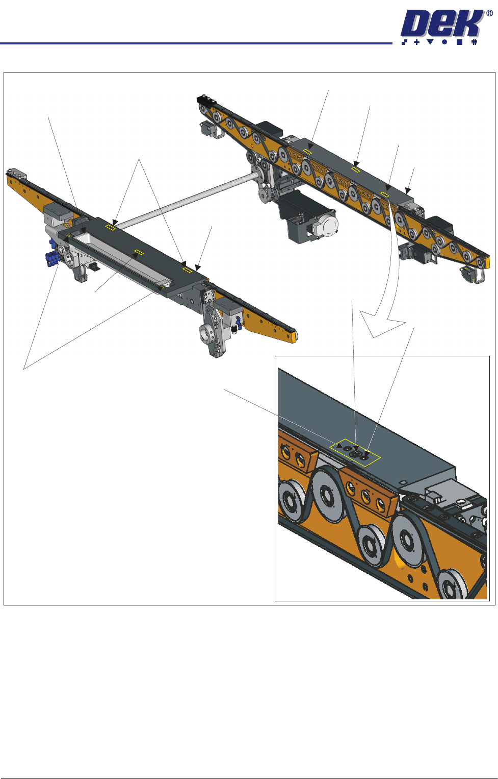
Adjustment (1) Screws (2)and Locking
Sphere Dump Tray
Rear Top Plate
Front Top Plate
Locking Screw
Locking Screw
Adjustment (1) and Locking Screws (2)
Adjustment (1) Screw
Adjustment (1) Screw
Safety Screws (2)
Adjustment (1)
Locking
and
Screws (2)
Adjustment Screw