WaferTransportSolutionManual.pdf - 第47页
HEAVY PALLET RAILS ADJUST MENTS & SE TTINGS Chapter Issue 1 August 11 Wafer Transport Solutio n 1.39 procedure for the rear top plate. 22. Place the gauge probe on the shim; the reading should be zero. Repeat the ste…
HEAVY PALLET RAILS
ADJUSTMENTS & SETTINGS
1.38 Wafer Transport Solution Chapter Issue 1 August 11
the readings change in accordance with manufactured tolerances indicated
on the setting bar. Setting bars have a surface flatness, on the engraved
side, of 20 microns.
9. Open the printhead front cover.
10. In the printer, ensure that all tooling has been removed from the tooling table
top.
11. Assemble the shim into the pallet and manually load both into the machine.
Slide it into the print position.
12. Close the printhead cover.
13. Press the System button.
14. Navigate to the Rail System module in Diagnostics.
15. Select Toggle Board Clamps. This holds the pallet in the correct location
and clamps it.
16. Press the E Stop.
17. Open the printhead front cover.
18. Loosen the two safety screws on the rear top plate to allow adjustment
without interference.
NOTE
The safety screws should remain either flush with or below the top surface
of the rear top plate.
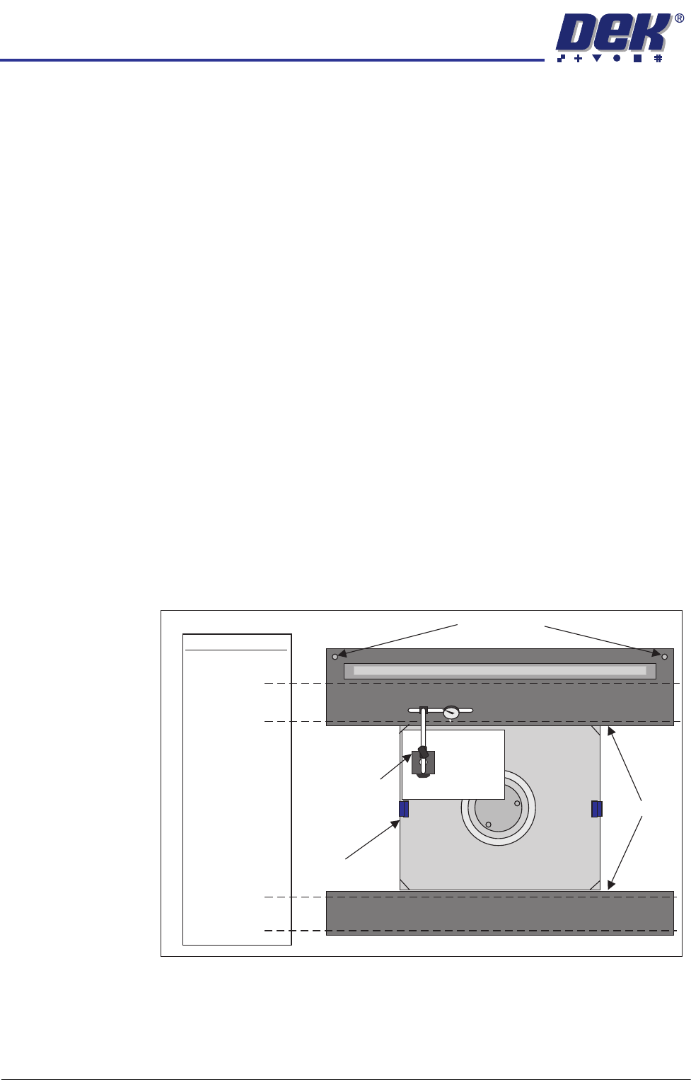
19. Place a sheet of paper on the pallet and shim to offer surface protection.
20. Sit the gauge assembly on the sheet of paper.
21. Carefully and slowly slide the gauge across the sheet of paper so that the
probe can float across the top surface of the front top plate. Reposition the
gauge and paper to carefully describe lines across the top plates at the
±0.025mm tolerance positions. Observe the reading for deviations from the
desired tolerance and note their magnitudes and locations. Repeat the
0.025mm
0.025mm
+
-
+
-
+
-
+
-
0.01mm
Step tolerance -
shim to top plate
0.01mm
Step tolerance -
shim to top plate
DTI and Stand
Tolerances
Safety Screws
Pallet and Shim
Top Plates
A3
Sheet
HEAVY PALLET RAILS
ADJUSTMENTS & SETTINGS
Chapter Issue 1 August 11 Wafer Transport Solution 1.39
procedure for the rear top plate.
22. Place the gauge probe on the shim; the reading should be zero. Repeat the
step above along the 0.01mm line.
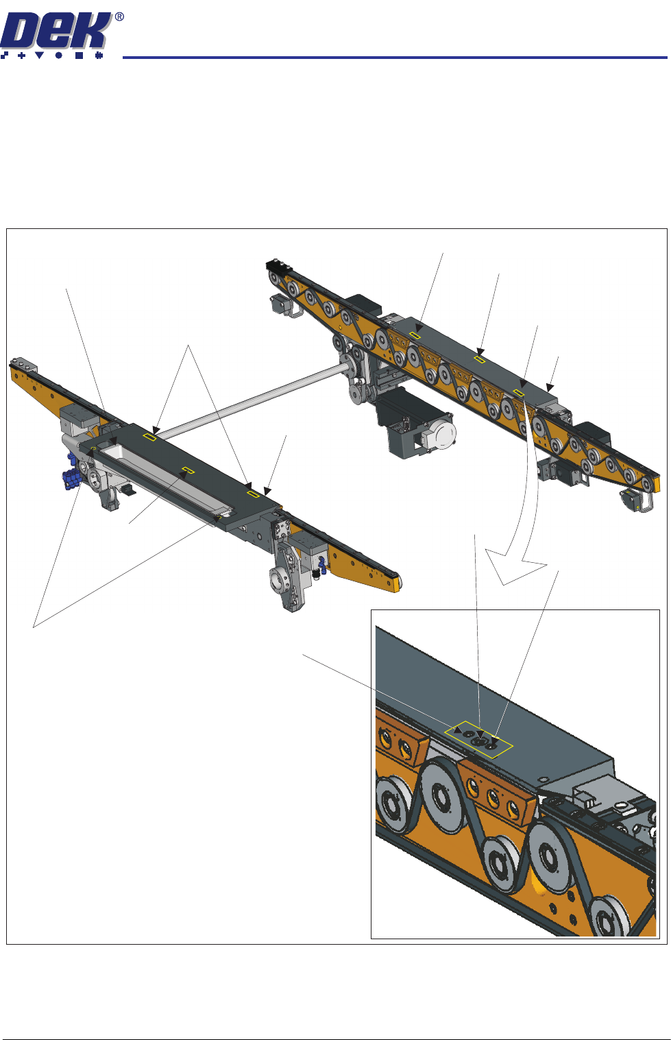
23. Make small adjustments, as required, to the front and rear top plate adjust-
ment screws, (do not unlock the associated locking screws) in the areas
which display out of tolerance results; only minor adjustments are neces-
sary.
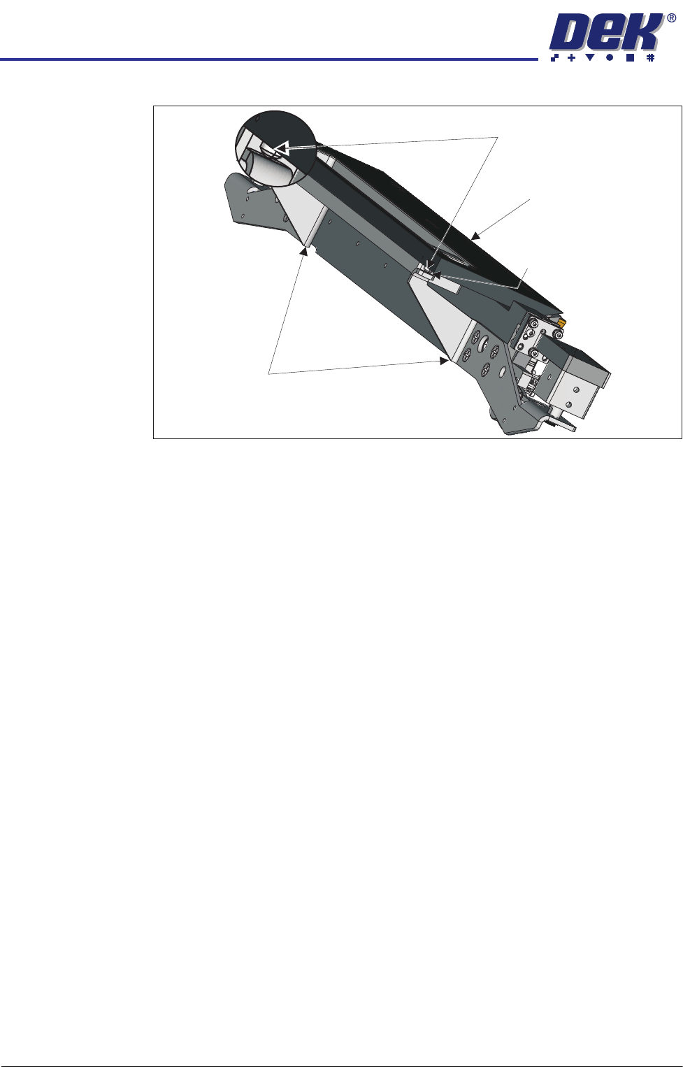
24. Wind the safety screws back down; use an 0.05mm feeler gauge to maintain
Adjustment (1) Screws (2)and Locking
Sphere Dump Tray
Rear Top Plate
Front Top Plate
Locking Screw
Locking Screw
Adjustment (1) and Locking Screws (2)
Adjustment (1) Screw
Adjustment (1) Screw
Safety Screws (2)
Adjustment (1)
Locking
and
Screws (2)
Adjustment Screw
HEAVY PALLET RAILS
ADJUSTMENTS & SETTINGS
1.40 Wafer Transport Solution Chapter Issue 1 August 11
a gap between the point of each screw and the lift cylinder arms.
25. Repeat Steps 20 and 21 to check the top plates remain within the stated
tolerance.
26. Remove the paper sheet and the gauge and the stand.
27. Close the printhead front cover.
28. Reset the E Stop.
29. Press the System button.
30. Select Toggle Board Clamps.
31. Open the printhead front cover.
32. Remove the pallet and shim.
33. Close the printhead front cover.
34. Press the System button.
Belt Tension This check is to set the correct transport belt tension.
Transport Belts
Front and Rear
Before proceeding, check that the transport belts are correctly wrapped onto the
pulleys.
1. Ensure that the stencil is removed from the machine.
2. Select the Rail System module in Diagnostics.
3. Using the Next/Previous buttons navigate to Belt Speed Calibration.
4. Set the front and rear belt speeds to 32000.
5. Select Incr. or Decr.
6. Confirm that the belt tracks correctly under tension and don’t ride up in the
pulleys.
7. Select Decr. or Incr. to reset to the correct value, prior to Step 5.
8. Select Exit.
Using a belt tension meter placed close to the lower section, in the centre of the
Lift Cylinder Arm
Maintain Gap0.05mm
Safety Screws
Rear Top Plate