WaferTransportSolutionManual.pdf - 第49页
HEAVY PALLET RAILS ADJUST MENTS & SE TTINGS Chapter Issue 1 August 11 Wafer Transport Solutio n 1.41 front belt, strum the belt and measure its frequency . The belt tension meter should have a reading between 28Hz to…
HEAVY PALLET RAILS
ADJUSTMENTS & SETTINGS
1.40 Wafer Transport Solution Chapter Issue 1 August 11
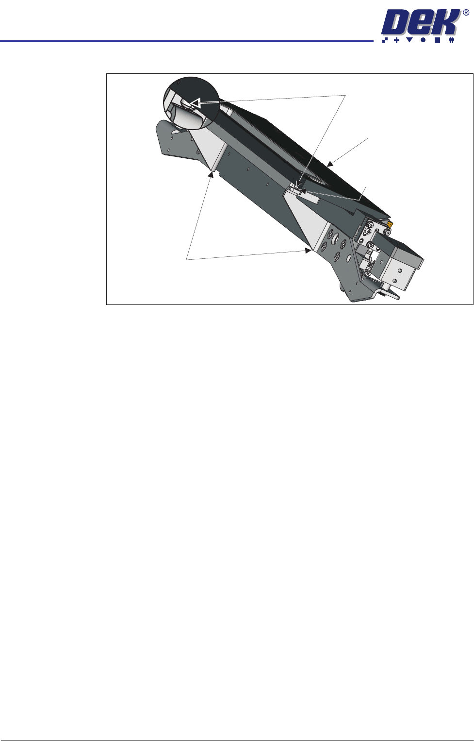
a gap between the point of each screw and the lift cylinder arms.
25. Repeat Steps 20 and 21 to check the top plates remain within the stated
tolerance.
26. Remove the paper sheet and the gauge and the stand.
27. Close the printhead front cover.
28. Reset the E Stop.
29. Press the System button.
30. Select Toggle Board Clamps.
31. Open the printhead front cover.
32. Remove the pallet and shim.
33. Close the printhead front cover.
34. Press the System button.
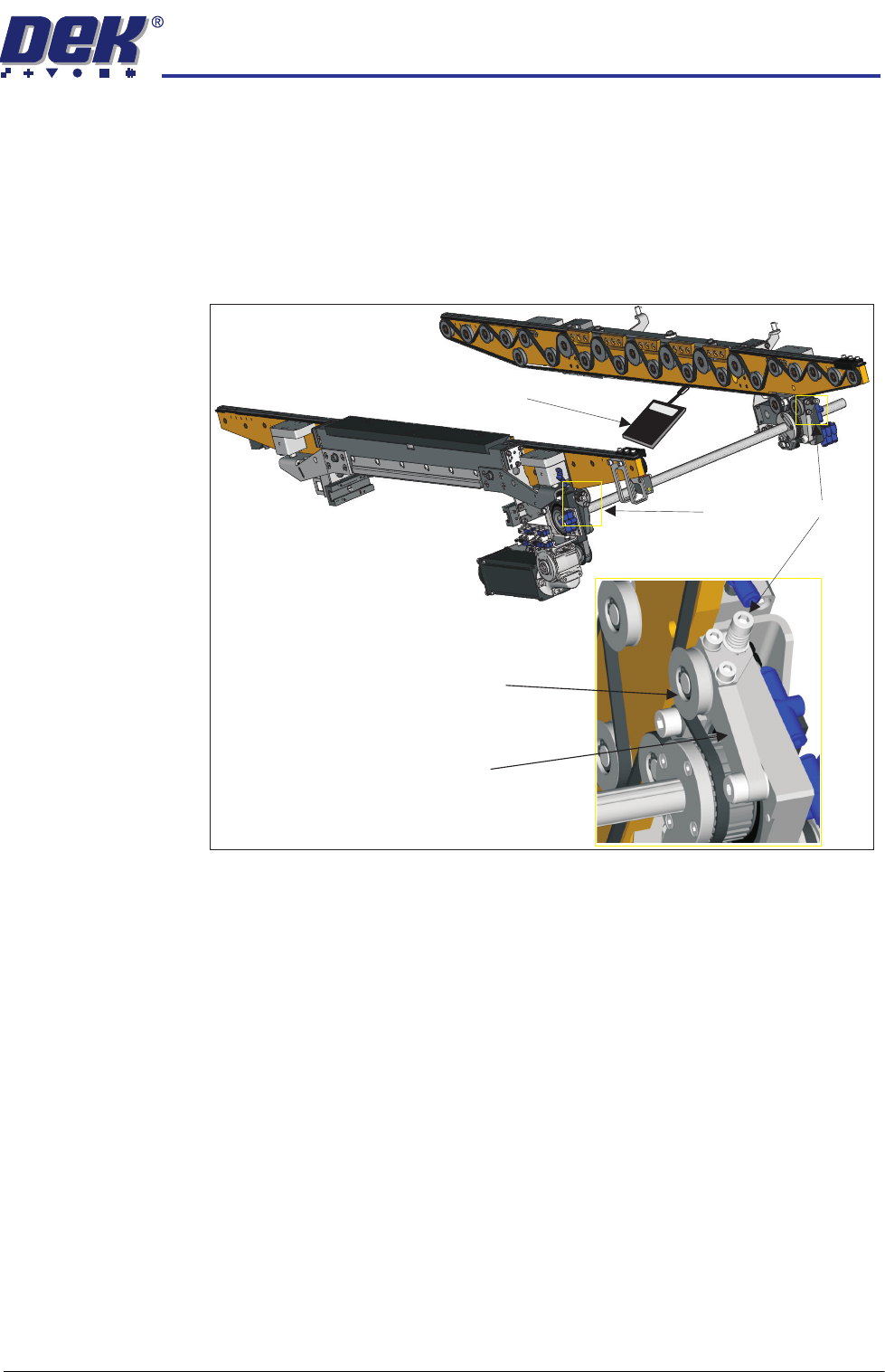
Belt Tension This check is to set the correct transport belt tension.
Transport Belts
Front and Rear
Before proceeding, check that the transport belts are correctly wrapped onto the
pulleys.
1. Ensure that the stencil is removed from the machine.
2. Select the Rail System module in Diagnostics.
3. Using the Next/Previous buttons navigate to Belt Speed Calibration.
4. Set the front and rear belt speeds to 32000.
5. Select Incr. or Decr.
6. Confirm that the belt tracks correctly under tension and don’t ride up in the
pulleys.
7. Select Decr. or Incr. to reset to the correct value, prior to Step 5.
8. Select Exit.
Using a belt tension meter placed close to the lower section, in the centre of the
Lift Cylinder Arm
Maintain Gap0.05mm
Safety Screws
Rear Top Plate
HEAVY PALLET RAILS
ADJUSTMENTS & SETTINGS
Chapter Issue 1 August 11 Wafer Transport Solution 1.41
front belt, strum the belt and measure its frequency. The belt tension meter
should have a reading between 28Hz to 32Hz.
9. If adjustment is needed; adjust the belt tensioner screw until the belt tension
is in the range stated. Turning the belt tensioner screw clockwise decreases
the tension.
10. Repeat Steps 2 through 8 to confirm that the belts track correctly.
11. Repeat Steps 7 through 11 for the rear pulley.
12. Select Exit.
Belt Tensioner Screw
Tension Pulley
Tension Lever
030
Belt Tension Meter
HEAVY PALLET RAILS
ADJUSTMENTS & SETTINGS
1.42 Wafer Transport Solution Chapter Issue 1 August 11
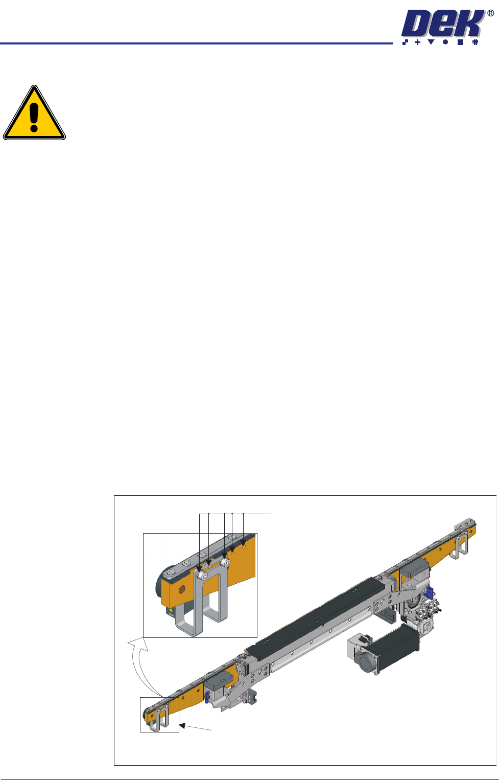
Sensor Repositioning
WARNING
HEAVY OBJECT. EXTREME CAUTION SHOULD BE EXERCISED WHEN
MANUALLY HANDLING HEAVY ITEMS INTO OR OUT OF THE MACHINE.
The input sensors are set to a nominal position. The position assumes that no
significant overrun occurs when the pallet exits the printer. This is product
dependent, and may in some instances result in the pallet stopping, near to or
over the exit of the printer.
NOTE
1. The machine exit can be on the same side as the input: (Left to Left or Right
to Right feed) or on the opposite side: (Right to Left or Left to Right feed)
dependent upon printer and upline/downline tool configurations.
2. Two processes are detailed. In the first, the DEK printer is working as a
stand alone unit and products are manually fed into the printer. In this
instance the amount of overrun is measured. In the second, the DEK
machine works with another in-line tool and the product is fed into and out
of the printer automatically; in this case a significant amount of overrun is
needed to ensure that the in-line tool can receive the product.
Sensor Positioning -
Manual Load
If significant overrun occurs:
1. Run the printer and measure the amount of overrun.
2. E-Stop the printer.
3. Remove the pallet.
4. Adjust the sensor position to compensate for the overrun. On both ends of
the front transport beam there are five mounting holes provided for adjust-
ment purposes; the bracket also has a slot to provide additional adjustment
between holes.
View on Front of Heavy Pallet Rails
Mounting holes in 5 positions
Sensor bracket (2 positions)