WaferTransportSolutionManual.pdf - 第51页
HEAVY PALLET RAILS ADJUST MENTS & SE TTINGS Chapter Issue 1 August 11 Wafer Transport Solutio n 1.43 5. Run the product and check for any ov errun. Re peat the procedure to fine tune the sensor position. Sensor Posit…
HEAVY PALLET RAILS
ADJUSTMENTS & SETTINGS
1.42 Wafer Transport Solution Chapter Issue 1 August 11
Sensor Repositioning
WARNING
HEAVY OBJECT. EXTREME CAUTION SHOULD BE EXERCISED WHEN
MANUALLY HANDLING HEAVY ITEMS INTO OR OUT OF THE MACHINE.
The input sensors are set to a nominal position. The position assumes that no
significant overrun occurs when the pallet exits the printer. This is product
dependent, and may in some instances result in the pallet stopping, near to or
over the exit of the printer.
NOTE
1. The machine exit can be on the same side as the input: (Left to Left or Right
to Right feed) or on the opposite side: (Right to Left or Left to Right feed)
dependent upon printer and upline/downline tool configurations.
2. Two processes are detailed. In the first, the DEK printer is working as a
stand alone unit and products are manually fed into the printer. In this
instance the amount of overrun is measured. In the second, the DEK
machine works with another in-line tool and the product is fed into and out
of the printer automatically; in this case a significant amount of overrun is
needed to ensure that the in-line tool can receive the product.
Sensor Positioning -
Manual Load
If significant overrun occurs:
1. Run the printer and measure the amount of overrun.
2. E-Stop the printer.
3. Remove the pallet.
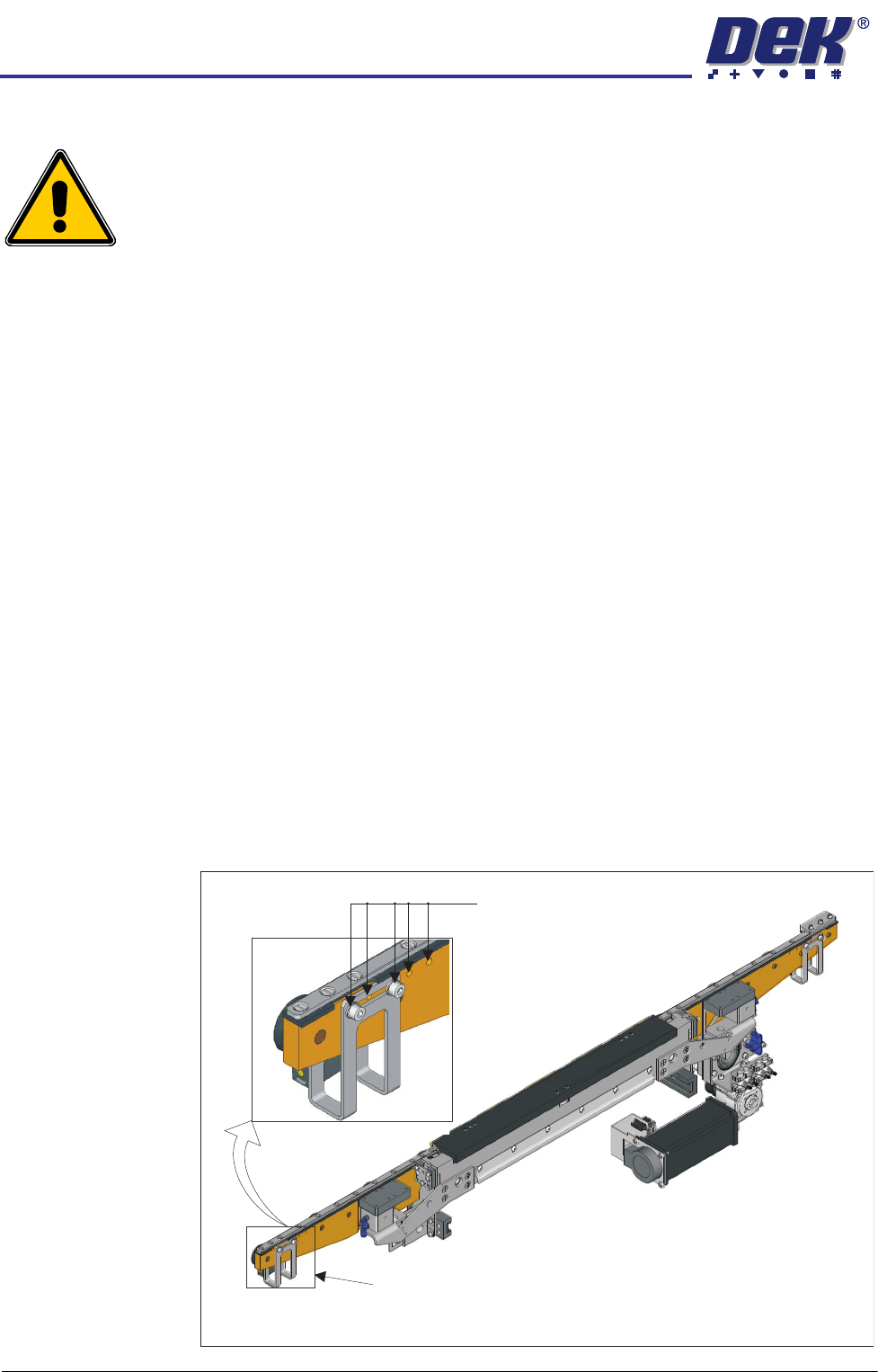
4. Adjust the sensor position to compensate for the overrun. On both ends of
the front transport beam there are five mounting holes provided for adjust-
ment purposes; the bracket also has a slot to provide additional adjustment
between holes.
View on Front of Heavy Pallet Rails
Mounting holes in 5 positions
Sensor bracket (2 positions)

HEAVY PALLET RAILS
ADJUSTMENTS & SETTINGS
Chapter Issue 1 August 11 Wafer Transport Solution 1.43
5. Run the product and check for any overrun. Repeat the procedure to fine
tune the sensor position.
Sensor Positioning
for Downline
Transfer
The placement of the sensor is product dependant (due to pallet, shim and
product mass). This must be adjusted on site to suit the product and reset, if
required, should a product change be made. Where downline transfer requires
a significant amount of the pallet to be fed back to the downline tool this
procedure should be followed.
NOTE
For an understanding of the logical timing sequences of the specific downline
tool interface, refer to the FMI chapter of the DEK Technical Reference Manual.
1. After the print process has finished, the belts feed the pallet in the direction
of the downline machine until the pallet’s leading edge reaches the rail end
sensor and the belts stop.
2. Both machines communicate via the FMI interface; the DEK printer awaits
the ready signal from the downline machine.
3. The belts rotate moving the pallet onto the downline equipment. The sensor
detects the trailing edge of the pallet. The belts stop.
4. The downline equipment takes control to transfer the pallet correctly.
In general, the sensor is positioned so that the transport belts in the DEK printer
stop when the sensor detects the trailing edge, and half of the pallet is located
in the downline machine.
HEAVY PALLET RAILS
ADJUSTMENTS & SETTINGS
1.44 Wafer Transport Solution Chapter Issue 1 August 11
Snugger Pressure Snugger pressure is set in production to give sufficient pressure to grip the pallet
without any lateral movement. The pressure regulator is located on the front
right hand side of the chase; the set pressure for an application should not be
altered. When a product change takes place, if the pallet used is significantly
different to the previous one, movement can occur.
1. Test for grip with the pallet in the rails with snugger pressure applied.
2. If the pallet can be moved, the pressure needs to be adjusted.
3. The pressure is nominally set to 3.45Bar.
4. If the pressure is set lower than this, increase it on the regulator to achieve
the nominal value.
5. Repeat Step 2 to check if lateral movement is still possible.
6. The recommended settings are shown in the table below.
Important. Do not exceed the highest setting; the maximum snugger
movement is 0.7mm. Over snugging causes unwanted stresses on the front
beam, affecting alignment offsets, causing misalignment issues on the rail.
Pressure Settings Regulator
Lowest Setting 80N @ 3.30Bar
Nominal Setting 100N @ 3.45Bar
Highest Setting 120N @ 3.60Bar