WaferTransportSolutionManual.pdf - 第56页
HEAVY PALLET RAILS CALIBRATIONS 1.48 Wafer Transport Solutio n Chapter Issue 1 August 11 CALIBRA TIONS Board Stop X Offset This procedure overwrites the st andard machine Board S top X Of fset setting. 1. Initialise the …
HEAVY PALLET RAILS
REPLACEMENT PROCEDURES
Chapter Issue 1 August 11 Wafer Transport Solution 1.47
Front Drive Belt To replace the front drive belt:
1. Ensure that the front transport belt has been removed first, see the previous
procedure.
2. Slacken off the four mounting bracket bolts using a 4mm Allen key.
3. Support the weight of the motor and remove the belt.
4. Fit the replacement belt.
5. While supporting the weight of the motor, ensure the motor is horizontal.
6. Allow the weight of the motor to tension the belt so that it rests in the teeth
of both pulleys.
7. Tighten the four mounting bracket bolts; ensure that the belt is centralised.
8. Refit the transport belts.
9. Refit the drive shaft.
Running Check Having reassembled the assemblies, test that the belts all run smoothly.
1. Select the Rail System module in Diagnostics.
2. Select Toggle Heavy Rail Drop. Ensure that the rail is up.
3. Select Belt Speed Calibration.
4. Select Incr. or Decr.
5. Confirm that the belt tracks correctly under tension and do not ride up in the
pulleys.
6. Select Decr. or Incr. to reset to the correct value.
7. Select Exit.
8. Tension the belts in accordance with the belt tension settings in the Adjust-
ments and Settings section of this Chapter.
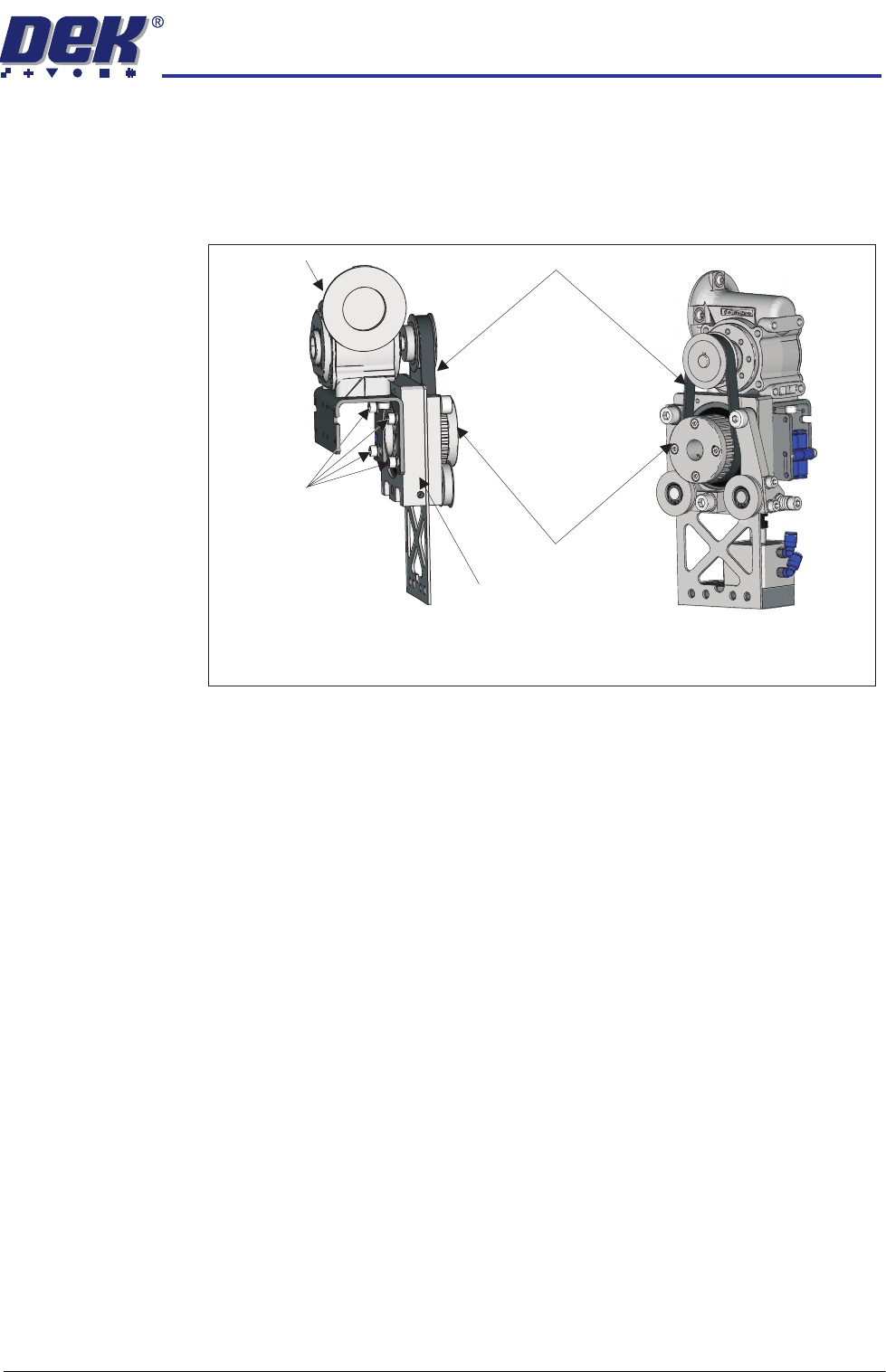
Drive Belt Mounting
Drive Mounting Viewed on Underside
Front Quarter View
Mounting
Bracket Bolts
Drive Belt
Driven Pulley Mount
Motor Mount
Driven Pulley
HEAVY PALLET RAILS
CALIBRATIONS
1.48 Wafer Transport Solution Chapter Issue 1 August 11
CALIBRATIONS
Board Stop X
Offset
This procedure overwrites the standard machine Board Stop X Offset setting.
1. Initialise the printer.
2. Select Load.
3. Load the Calibra. file.
4. Select Back.
5. Press the System button.
6. Select Maintenance.
7. Select Machine Setup.
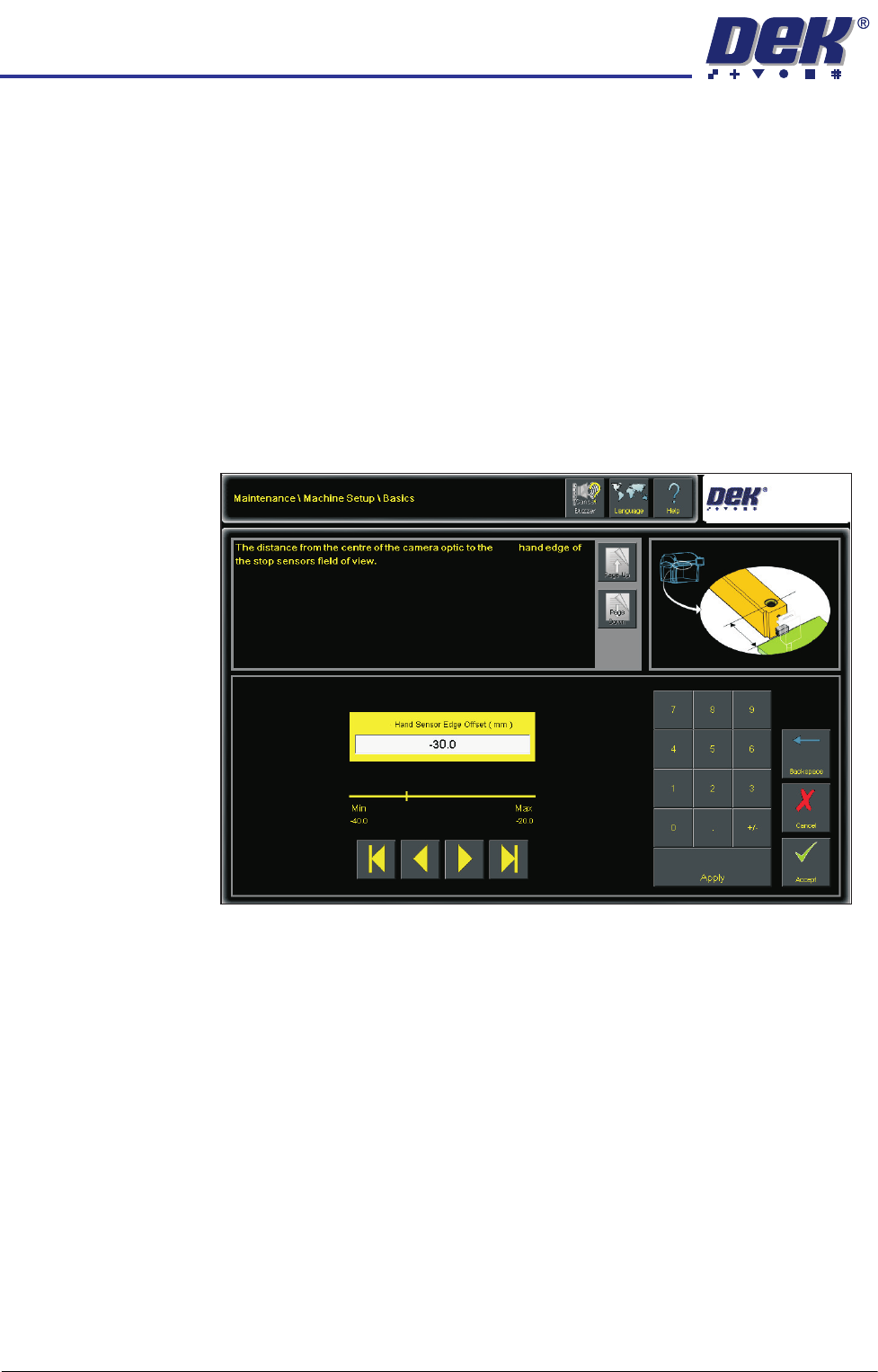
8. Select Basics.
9. Select Left Hand Sensor Edge Offset.
NOTE
This is dependent upon whether or not the printer is set up for left to right or
right to left operation. For right to left operation, the setting would be: Right
Hand Sensor Edge Offset.
10. Set to -30mm.
11. Select Accept.
12. Select Back.
13. Select Back.
14. Select Back.
15. Place the calibration board (part number 201149) on the input rails and set
up the printer ready to print.
16. Select Maintenance.
17. Select Calibrations.
18. Select Board Stop Sensor.
Left
Left

HEAVY PALLET RAILS
CALIBRATIONS
Chapter Issue 1 August 11 Wafer Transport Solution 1.49
19. Select Calib. Sensor. The board loads; the camera moves to a position
roughly at the centre of the printer. The vision window displays the location
of the board centre ident (circle).
20. Using the jog buttons locate the circular ident at the centre of the board.
21. Select Confirm. The system carries out an automated cycle, checking the
left and right edges of the board, setting automatic values for the sensor
offset.
Pre-check Before
Standard
Calibration
This procedure sets the deceleration rate for the non-contact board stop.
1. Initialise the printer.
2. Select Load.
3. Load the Calibra. file.
4. Select Back.
5. Press the System button.
6. Select Setup Product.
7. Select Board Thickness and set to 5mm.
8. Select Load Product.
9. Select 265test1.
10. Select Load.
11. Select Back.
12. Select Board Thickness and set to 5mm. This must be set before
calibrating vision height.
13. Select Back.
14. On the user interface navigate to the Diagnostics page and select the
Rising Table module.
15. Select Restore Default Heights. Important. Printer damage may occur if
this step is not carried out.
16. Select Exit.
17. Select Back.
18. Complete the following calibrations as detailed in the machine’s technical
reference manual set:
a. Vision Height Calibration
b. Print Reference Height
c. Reference Position