WaferTransportSolutionManual.pdf - 第61页
PRECISION WAFER PALLET MECHANICAL DETAIL Chapter Issue 1 Aug 11 Wafer Transport Solutio n 2.3 MECHANICAL DET AIL Precision W afer Pallet Figure 2-2 Precision W afer Pallet Item Description Item Description 1 W afer Palle…

PRECISION WAFER PALLET
OVERVIEW
2.2 Wafer Transport Solution Chapter Issue 1 Aug 11
Sequence The precision wafer pallet has four porous concentric vacuum rings. An
external downline vacuum system, secures the wafer and an aligning shim to
the pallet. Where small products are being processed, the shim masks off the
outer porous rings. To release the wafer from the pallet, a vacuum driven lift
mechanism is used; an external wafer handling system provides the means to
pick up the wafer and transfer it to the next in line machine tool.
1. The pallet and wafer enter the machine on the rail’s transport belts; the pallet
has overhanging edges which sit on the transport rails.
2. A non-contact board stop system positions the pallet beneath the screen.
3. Four beam lift cylinders, fitted to the transport beams, retract. The transport
belts drop depositing the pallet onto pallet support blocks.
4. The pallet snugger plate moves forward to hold the pallet in position.
5. Based on a fiducial scan performed by the camera, the machine aligns the
screen to the pallet.
6. The rising table lifts the rails, and pallet, to print height.
7. The print cycle commences.
8. Following the print operation, the rails and pallet lower with the rising table.
9. The pallet snugger rail moves back to release the pallet.
10. The beam lift cylinders extend to lift the pallet off the support blocks.
11. The transport belts carry the pallet and wafer back to the external downline-
system.
12. The holding vacuum switches off.
13. The vacuum release pin lift mechanism is actuated by the external handler
system. The three pins on the lift mechanism rise through the pallet,
releasing the wafer out of the shim.
14. The downline system removes the wafer and transports it to the next in line
tool.
15. The vacuum release pin lift mechanism retracts.
16. The pallet is moved back to the downline equipment and a new blank wafer
is delivered.
The sequence repeats until all wafers have printed.
PRECISION WAFER PALLET
MECHANICAL DETAIL
Chapter Issue 1 Aug 11 Wafer Transport Solution 2.3
MECHANICAL DETAIL
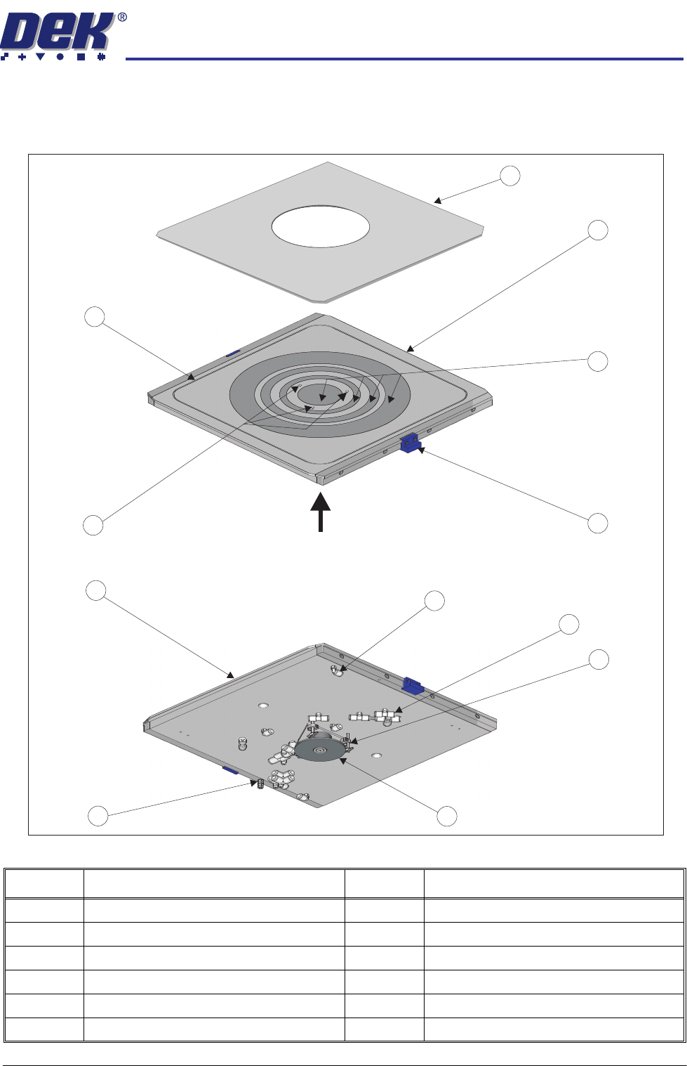
Precision Wafer Pallet
Figure 2-2 Precision Wafer Pallet
Item Description Item Description
1 Wafer Pallet Aligning Shim 7 Shim Groove Connector (2 Positions)
2 Wafer Pallet 8 Porous Segment Vacuum Connectors
3 Porous Vacuum Segments 9 Vacuum Pin (3 Positions)
4 Positioning Block (2 Positions) 10 Vacuum Pin Lift Mechanism
5 Wafer Release Pin Holes 11 Ground/Earth Point
6 Shim Vacuum Groove 12 Pallet Overhang Edge (2 Positions)
A
View from Top of Precision Wafer Pallet
View on A
1
2
4
3
5
6
8
9
10
11
12
7
PRECISION WAFER PALLET
MECHANICAL DETAIL
2.4 Wafer Transport Solution Chapter Issue 1 Aug 11
System Components
Pneumatic Tubing The precision wafer pallet is linked by three coiled tubes from the downline
system. The tubes extend far enough for the pallet to be fed from the printer
input rails to its output rails.
Using a combination of tubes, connectors and blanking plugs, on the
underside of the pallet, the system can be set up to suit the size and type of
wafer to be printed.
Lift Mechanism The lift mechanism has three pins which rise vertically on a central bearing,
from just below the top surface of the pallet, to several millimetres above. In
the up position, the wafer is easily loaded/unloaded from the pallet. When the
mechanism lowers, the wafer is bought gently into contact with the pallet
inside the shim’s central aperture. At the top of each pin, vacuum cups are
used to contact and retain the wafer. Vacuum is supplied via connectors
located under the pallet. When the wafer has been removed by the downline
system, the vacuum is switched off and the spring forces the lift mechanism
back down.
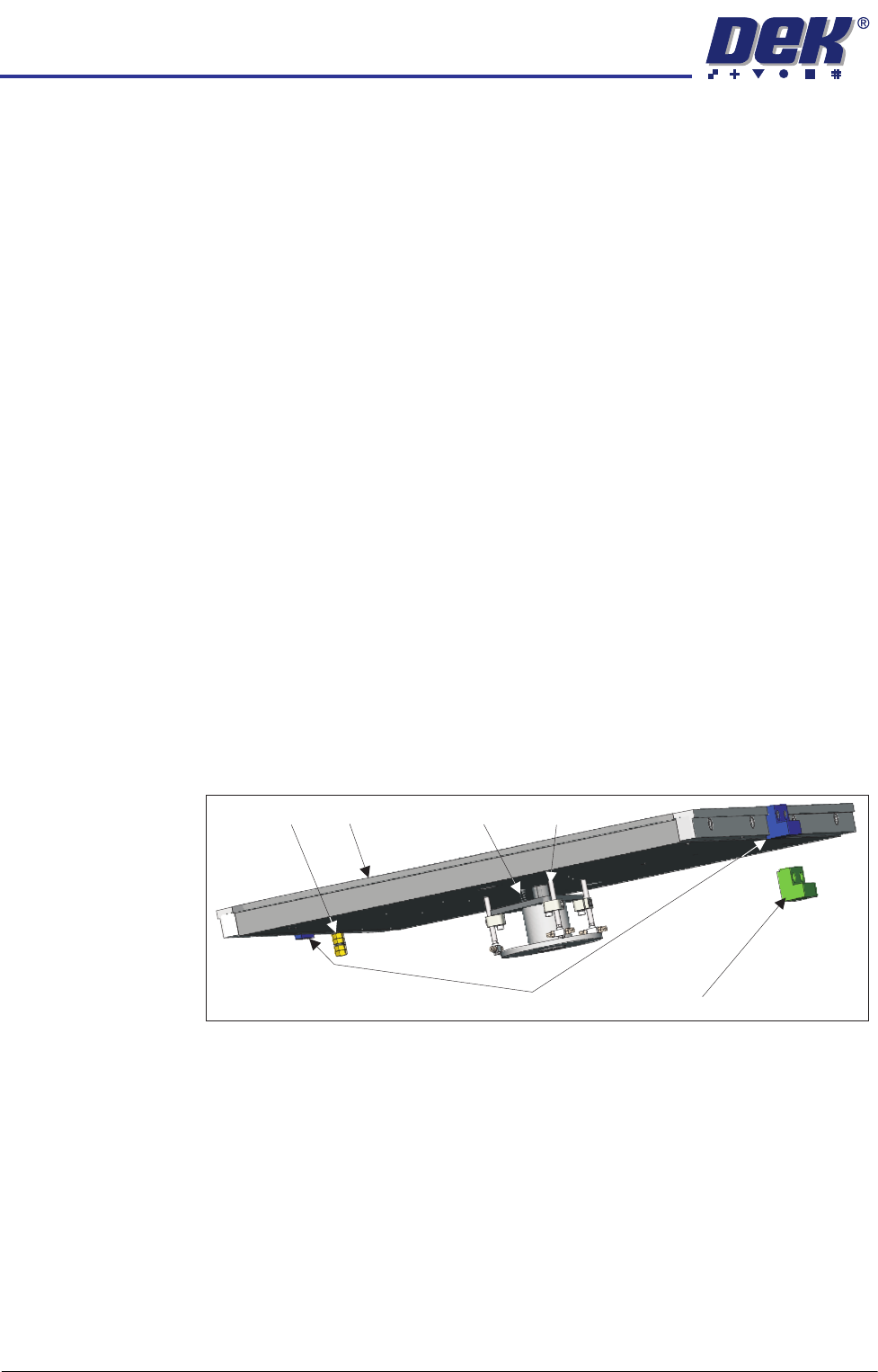
Shim Locate Blocks There are two shim locate block types: identified by blue or green body. Blue
blocks are used when loading from the left side of the printer, whilst green
blocks are used when the pallet is loaded from the right hand side.
Blocks should always be used as a matching pair; the pallet should be loaded
with the pneumatic manifold on the trailing edge and the larger of the two
locate blocks is on the leading edge.
The shim locate blocks are height adjustable and should be set high enough to
locate the shim but not higher than the shim (70 to 90% of shim thickness).
They are factory set to a height above the pallet of 0.34mm ± 0.04mm.
Earth Stud The metalwork of the pallet can be earthed by connecting an earthing lead to
the earth stud. This is used to neutralise any static that may build up on the
assembly as a result of moving it in to and out of the printer.
Shim The shim is used to mask areas of the pallet not occupied by the wafer. A
rectangular groove, on the top face of the pallet, applies holding vacuum to the
shim; this prevents it from slipping. Two shim locate blocks, at the feed-in and
feed-out edges of the pallet, are used to position the shim accurately.
NOTE
Feed in and feed out refers to the direction of travel from the downline machine
into and out of the printer. The actual edge referred to depends upon the feed
direction set up for the printer (left to right, right to left, left to left or right to right).
Shim Locate Block (Left)
Pallet
Lift Mechanism
Return Spring
Earth Stud
Shim Locate Block (Right)