WaferTransportSolutionManual.pdf - 第63页
PRECISION WAFER PALLET MECHANICAL DETAIL Chapter Issue 1 Aug 11 Wafer Transport Solutio n 2.5 V acuum V acuum is used to: • Secure the shim • Supply the porous e lements, which hold th e wafer • Supply the vacuum cu ps o…
PRECISION WAFER PALLET
MECHANICAL DETAIL
2.4 Wafer Transport Solution Chapter Issue 1 Aug 11
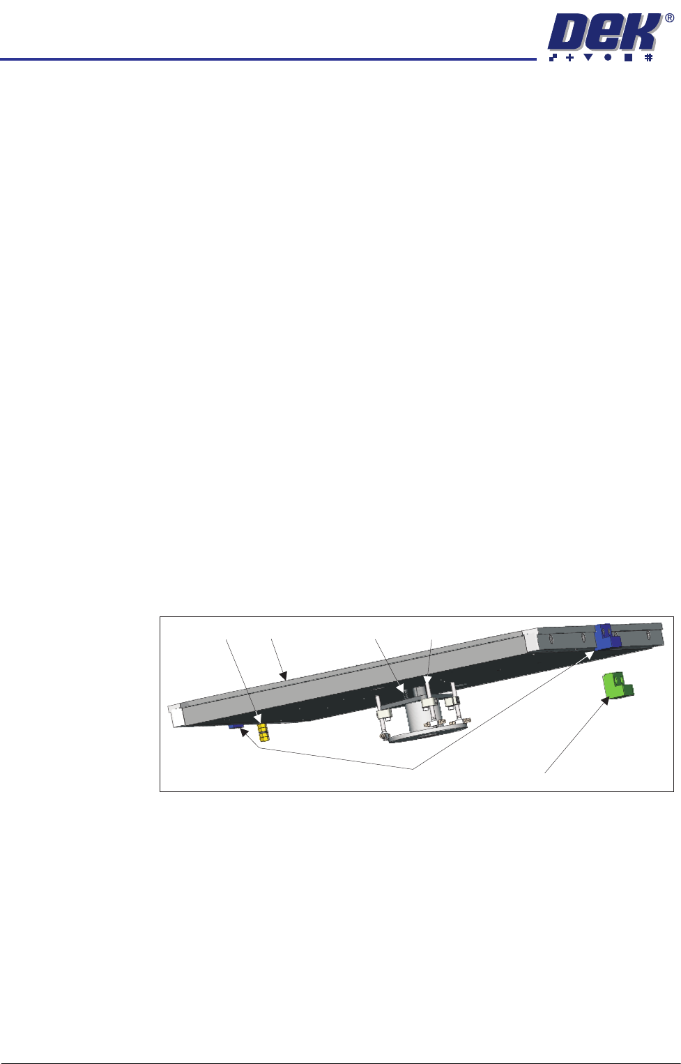
System Components
Pneumatic Tubing The precision wafer pallet is linked by three coiled tubes from the downline
system. The tubes extend far enough for the pallet to be fed from the printer
input rails to its output rails.
Using a combination of tubes, connectors and blanking plugs, on the
underside of the pallet, the system can be set up to suit the size and type of
wafer to be printed.
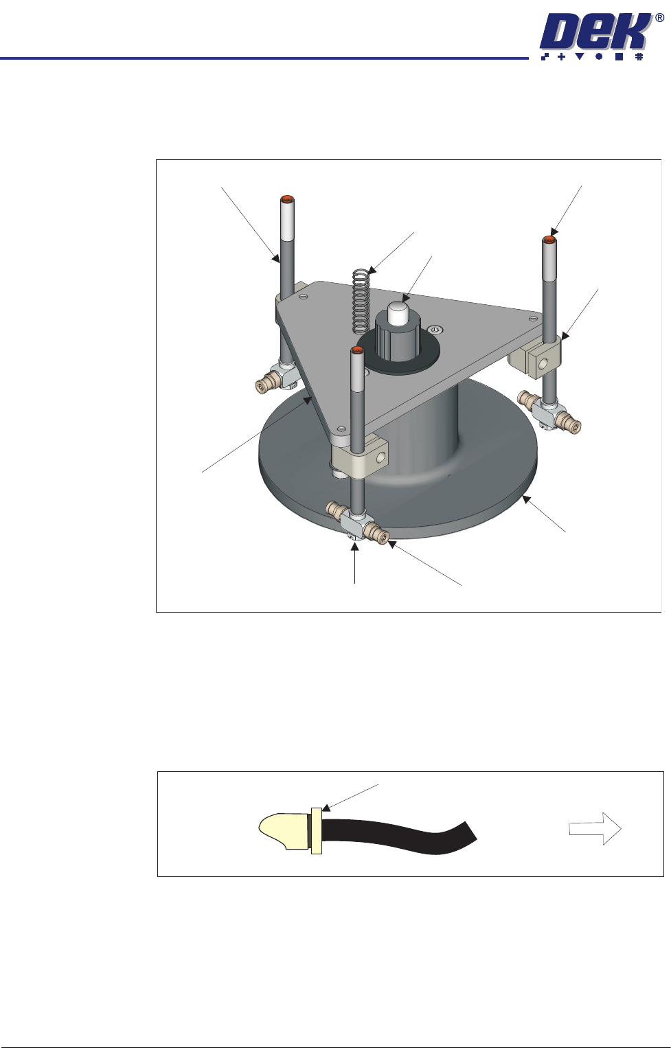
Lift Mechanism The lift mechanism has three pins which rise vertically on a central bearing,
from just below the top surface of the pallet, to several millimetres above. In
the up position, the wafer is easily loaded/unloaded from the pallet. When the
mechanism lowers, the wafer is bought gently into contact with the pallet
inside the shim’s central aperture. At the top of each pin, vacuum cups are
used to contact and retain the wafer. Vacuum is supplied via connectors
located under the pallet. When the wafer has been removed by the downline
system, the vacuum is switched off and the spring forces the lift mechanism
back down.
Shim Locate Blocks There are two shim locate block types: identified by blue or green body. Blue
blocks are used when loading from the left side of the printer, whilst green
blocks are used when the pallet is loaded from the right hand side.
Blocks should always be used as a matching pair; the pallet should be loaded
with the pneumatic manifold on the trailing edge and the larger of the two
locate blocks is on the leading edge.
The shim locate blocks are height adjustable and should be set high enough to
locate the shim but not higher than the shim (70 to 90% of shim thickness).
They are factory set to a height above the pallet of 0.34mm ± 0.04mm.
Earth Stud The metalwork of the pallet can be earthed by connecting an earthing lead to
the earth stud. This is used to neutralise any static that may build up on the
assembly as a result of moving it in to and out of the printer.
Shim The shim is used to mask areas of the pallet not occupied by the wafer. A
rectangular groove, on the top face of the pallet, applies holding vacuum to the
shim; this prevents it from slipping. Two shim locate blocks, at the feed-in and
feed-out edges of the pallet, are used to position the shim accurately.
NOTE
Feed in and feed out refers to the direction of travel from the downline machine
into and out of the printer. The actual edge referred to depends upon the feed
direction set up for the printer (left to right, right to left, left to left or right to right).
Shim Locate Block (Left)
Pallet
Lift Mechanism
Return Spring
Earth Stud
Shim Locate Block (Right)

PRECISION WAFER PALLET
MECHANICAL DETAIL
Chapter Issue 1 Aug 11 Wafer Transport Solution 2.5
Vacuum Vacuum is used to:
• Secure the shim
• Supply the porous elements, which hold the wafer
• Supply the vacuum cups on the lift pins
The vacuum supplied to the shim is constant, this keeps it in place for the
complete print run whereas, that supplied to both the lift mechanism and the
wafer are switchable. Vacuum switching is provided externally by the downline
system. The downline system automatically switches the vacuum off, when
the wafer is to be released, after printing, and it switches it back on again when
a wafer is ready for transfer to the DEK printer.
PRECISION WAFER PALLET
REPLACEMENT PROCEDURES
2.6 Wafer Transport Solution Chapter Issue 1 Aug 11
REPLACEMENT PROCEDURES
Lift Pin
Replacement
The lift mechanism has three lift pins which, when worn or damaged, may be
replaced. The lift pins are connected directly to the vacuum system.
1. Isolate the downline system from the pneumatic air input.
2. Open the transfer station’s front cover to access the pallet on the conveyor.
3. Turn the pallet face side down on the conveyor to access the two pneumatic
lines connected to the base of the pallet.
4. Remove the three pneumatic input lines by depressing the fitting end collar
and removing the push fit tubing.
5. Remove the pallet from the machine and place it face side down on a
protective cloth.
6. Disconnect the vacuum tubing on the lift pin vacuum connector.
7. Loosen the clamp locking screw.
8. Remove the lift pin from the clamp.
Ball Spline Shaft
Clamp
Vacuum Connector
Flat Bladed Screwdriver Here
(See Text)
Lift
Mechanism
Housing
Pin
Lift
Plate
Vacuum Cup
Return Spring
Lift Pin
Depress End Collar
Remove Tubing
Pneumatic Fitting