WaferTransportSolutionManual.pdf - 第83页
INSTALLATION EQUIPMENT INSTALLATION Chapter Issue 1 Aug 11 Wafer Transport Solutio n 3.7 EQUIPMENT INST ALLA TION CHAD and NUTEK Equipment Reference should be made to the technical and inst allation dat a provided by the…
INSTALLATION
OVERVIEW
3.6 Wafer Transport Solution Chapter Issue 1 Aug 11
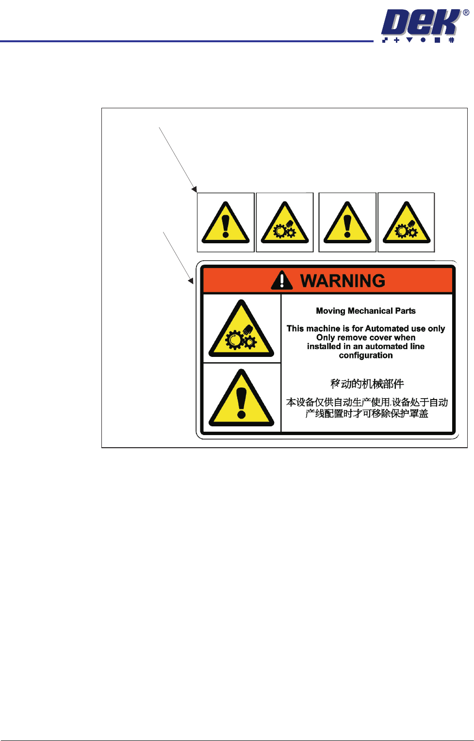
Labels Warning labels are placed on the machine in areas where a potential hazard
may exist.
Situated behind the safety covers
Situated on the
safety covers

INSTALLATION
EQUIPMENT INSTALLATION
Chapter Issue 1 Aug 11 Wafer Transport Solution 3.7
EQUIPMENT INSTALLATION
CHAD and NUTEK Equipment
Reference should be made to the technical and installation data provided by
the wafer handling equipment manufacturers. This manual gives a brief
overview of the specific equipment proposed by DEK for this application.
Information provided in this manual is for guidance only. DEK suggests that
users familiarise themselves with the specific instructions on safety,
installation, maintenance and operation of any equipment placed in-line with
the DEK printer(s).
The section below describes the services required to interface the wafer
handling equipment to the DEK printer.
Services In order for the conveyor to function correctly the following services must be
available:
• Electrical Supply
• Pneumatic Supply
• Upline/Downline Machine Interface (FMI)
The services required for both equipment types are shown below:
NUTEK Refer to linking conveyor manual: NTM410L-1000-1(S)
Electrical The mains input, to the linking conveyor, is fed directly from a separate factory
mains wall outlet.
The conveyor operates on 230VAC/50Hz single phase ac mains or 110VAC/
60Hz single phase ac mains.
Pneumatic The conveyor requires a pneumatic supply of clean, non lubricated air which
should maintain a minimum pressure 5 Bar and a maximum of 8 Bar.
The air should be to ISO 8573.1 standard, quality class 2.3.3, where:
• 2 dirt = 1 micron
• 3 water = -20°C pressure dewpoint
• 3 oil = 1mg/m3
The air supply, from the optional services panel at the rear of the host printer,
is fed to the input connector of the linking conveyor where it is directly
connected to the regulator. The regulator is set to 5 Bar.
Interface The conveyor interface (FMI) is via standard SMEMA protocol. The FMI pod
on the host printer connects via M28SK02 to a pair of connectors PLA/PLB of
the respective upstream and downstream connectors.

INSTALLATION
EQUIPMENT INSTALLATION
3.8 Wafer Transport Solution Chapter Issue 1 Aug 11
CHAD Work Mate
Range
Refer to Wafermate 300-2. 1 Transfer Station; Drawing No. 520588.
NOTE
If a 125 to 200mm conveyor system is used refer to the Wafermate 300-3 data
sheet.
Electrical The mains input, to the WM 300-2, is fed directly from a separate factory
mains wall outlet.
The WM 300-2 operates on 200 to 240VAC/50Hz, 20amps, single phase ac
mains.
Pneumatic The WM 300-2 requires a pneumatic supply of clean, non lubricated air which
should maintain a minimum pressure 5 Bar and a maximum of 8 Bar.
The air should be to ISO 8573.1 standard, quality class 2.3.3, where:
• 2 dirt = 1 micron
• 3 water = -20°C pressure dewpoint
• 3 oil = 1mg/m3
The air supply, from the optional services panel at the rear of the host printer,
is fed to the input connector of the WM 300-2 where it is directly connected to
the regulator. The regulator is set to 6 Bar.
Interface The WM 300-2 interface (FMI) is via standard SMEMA protocol. The FMI pod
on the host printer connects via M28SK02 to a pair of connectors PLA/PLB of
the respective upstream and downstream connectors.