WaferTransportSolutionManual.pdf - 第89页
INSTALLATION EQUIPMENT INSTALLATION Chapter Issue 1 Aug 11 Wafer Transport Solutio n 3.13 4. The pallet is positioned ensuring it co vers both alignment sensors. 5. The keyswitch mode is as follows: a. MODE1 is Lef t to …
INSTALLATION
EQUIPMENT INSTALLATION
3.12 Wafer Transport Solution Chapter Issue 1 Aug 11
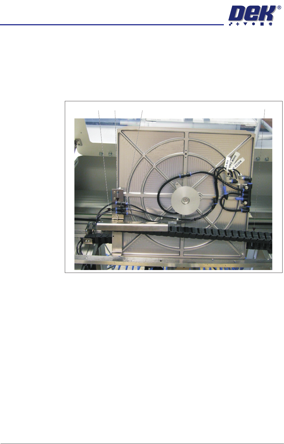
2. The empty pallet is placed inside the conveyer so the user can connect the
pneumatic pipes to:
•Pin Vac
•Wafer Vac
•Shim Vac
The flying leads are in the drag chain.
3. The pallet is laid flat onto the transport rails and a shim is placed on the
pallet.
Pin Vac
Shim Vac Wafer Vac Drag Chain
INSTALLATION
EQUIPMENT INSTALLATION
Chapter Issue 1 Aug 11 Wafer Transport Solution 3.13
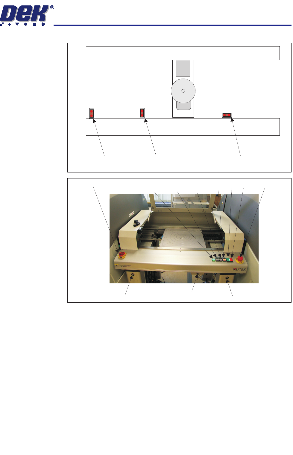
4. The pallet is positioned ensuring it covers both alignment sensors.
5. The keyswitch mode is as follows:
a. MODE1 is Left to Left conveyor operation
b. MODE 2 is Left to Left and Right to Right operation (feeding two printers)
c. Mode 3 is Right to Right conveyor operation
The operator selects the correct mode for the operation.
6. Switch the mains isolator ON. The green power lamp comes ON.
7. Press the green ON button. The vacuum pins raise.
8. Load the wafer onto the pins.
Rail End Sensor
Left Alignment Sensor Right Alignment Sensor
Rail Width Adjuster Rail Width AdjusterKey Switch
Mains Isolator
E Stop
Power
Lamp Vacuum Vacuum
Start Plate Reset ON OFF

INSTALLATION
EQUIPMENT INSTALLATION
3.14 Wafer Transport Solution Chapter Issue 1 Aug 11
9. Users can decide the alignment options, with reference to stencil/screen
artwork design; however, DEK suggest following the procedure below:
a. Make an alignment mark, on the shim, measured 45 degrees above
horizontal as shown.
b. Align the wafer notch or pattern to the alignment mark.
10. Close the front cover.
11. Press PLATE Vacuum. The Plate Vacuum button light is ON. The pins
retract. Shim vacuum holds the shim in place.
12. Press START Vacuum. The Start Vacuum button light is ON. The pallet
moves to the selected conveyor output. If the printer is ready to demand a
product, the pallet transfers into the printer.
13. After printing, the pallet transfers back to the NUTEK Linking Conveyor.
14. If the keyswitch is set to Mode 1 or 3 the front cover can be opened. The
printed wafer is removed and a blank wafer is loaded. If the keyswitch is set
to mode 2 the pallet is transferred to the ball placement printer for process-
ing. On completion, the pallet is returned to the conveyor.
15. Remove the wafer and restart the cycle for the next wafer.
Wafer Notch Aligned Wafer Pattern Aligned
45
0
Alignment Mark
45
0