WaferTransportSolutionManual.pdf - 第91页
INSTALLATION EQUIPMENT INSTALLATION Chapter Issue 1 Aug 11 Wafer Transport Solutio n 3.15 Inst allation Procedure T ransit Bracket s There are no addit ional transit bracket s fitted to the WTS printer , however DEK reco…

INSTALLATION
EQUIPMENT INSTALLATION
3.14 Wafer Transport Solution Chapter Issue 1 Aug 11
9. Users can decide the alignment options, with reference to stencil/screen
artwork design; however, DEK suggest following the procedure below:
a. Make an alignment mark, on the shim, measured 45 degrees above
horizontal as shown.
b. Align the wafer notch or pattern to the alignment mark.
10. Close the front cover.
11. Press PLATE Vacuum. The Plate Vacuum button light is ON. The pins
retract. Shim vacuum holds the shim in place.
12. Press START Vacuum. The Start Vacuum button light is ON. The pallet
moves to the selected conveyor output. If the printer is ready to demand a
product, the pallet transfers into the printer.
13. After printing, the pallet transfers back to the NUTEK Linking Conveyor.
14. If the keyswitch is set to Mode 1 or 3 the front cover can be opened. The
printed wafer is removed and a blank wafer is loaded. If the keyswitch is set
to mode 2 the pallet is transferred to the ball placement printer for process-
ing. On completion, the pallet is returned to the conveyor.
15. Remove the wafer and restart the cycle for the next wafer.
Wafer Notch Aligned Wafer Pattern Aligned
45
0
Alignment Mark
45
0
INSTALLATION
EQUIPMENT INSTALLATION
Chapter Issue 1 Aug 11 Wafer Transport Solution 3.15
Installation Procedure
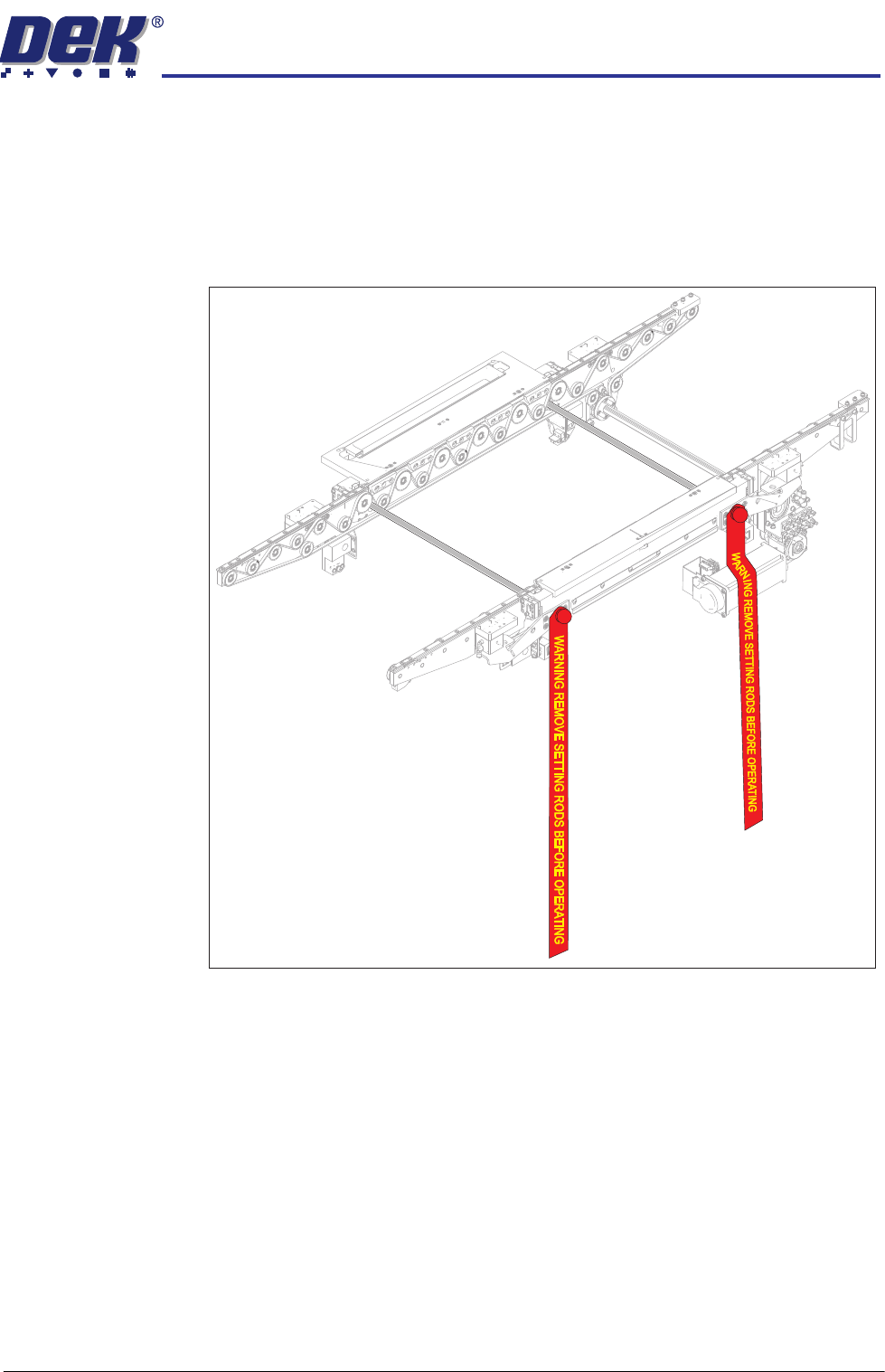
Transit Brackets There are no additional transit brackets fitted to the WTS printer, however DEK
recommend that the setting rods are fitted when the printer is being relocated.
All transit brackets and setting rods should be removed prior to powering up
the printer.
Figure 3-6 Setting Rods Located in the Transport Rails
Place the Printer in
Line
The instructions for lifting and moving the printer(s) are given in the printer
installation manual.
INSTALLATION
EQUIPMENT INSTALLATION
3.16 Wafer Transport Solution Chapter Issue 1 Aug 11
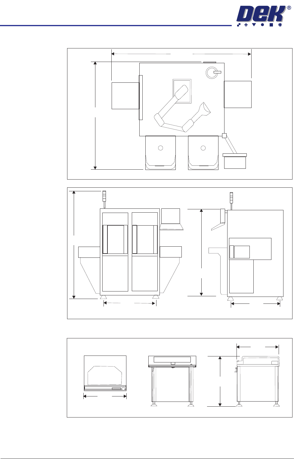
The CHAD WaferMate dimensions are as shown in the graphics below.
The NUTEK Linking Conveyor dimensions are shown below.
Ensure that the first equipment in the line is installed correctly and is level.
The printer(s) are to be levelled such that the transport rails, from one machine
to the next, are all in-line and level. To level the printer carry out the following
procedure.
WaferMate Plan View
1896
1493
WaferMate Front View
WaferMate End View
931
826
2032
1472
Front View
Plan View
End View
1000
802
950 +/- 25