WaferTransportSolutionManual.pdf - 第92页
INSTALLATION EQUIPMENT INSTALLATION 3.16 Wafer Transport Solutio n Chapter Issue 1 Aug 11 The CHAD W aferMate dimensions are as shown in the graphics below . The NUTEK Linking Conveyor dimensions are shown below . Ensure…
INSTALLATION
EQUIPMENT INSTALLATION
Chapter Issue 1 Aug 11 Wafer Transport Solution 3.15
Installation Procedure
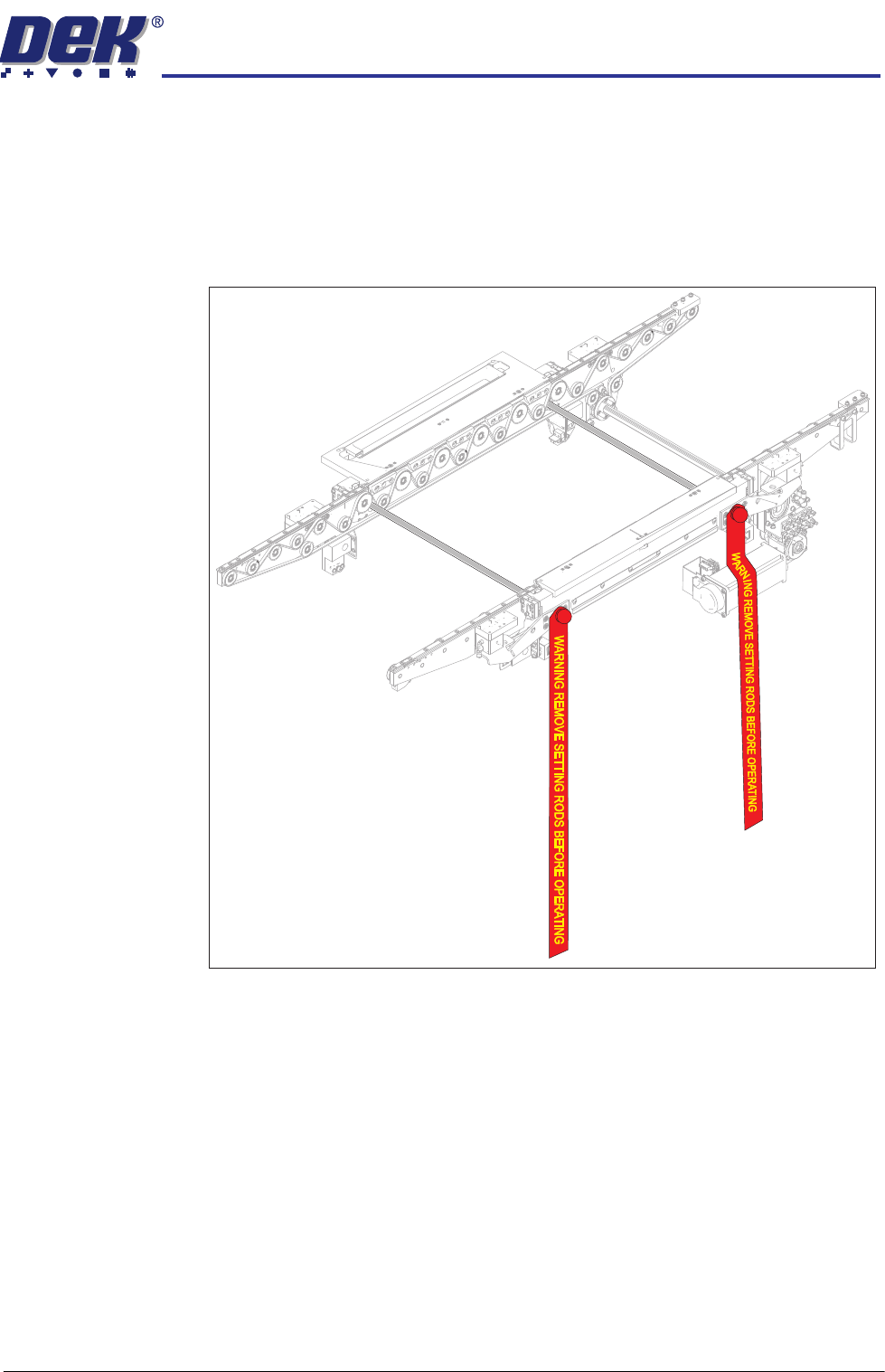
Transit Brackets There are no additional transit brackets fitted to the WTS printer, however DEK
recommend that the setting rods are fitted when the printer is being relocated.
All transit brackets and setting rods should be removed prior to powering up
the printer.
Figure 3-6 Setting Rods Located in the Transport Rails
Place the Printer in
Line
The instructions for lifting and moving the printer(s) are given in the printer
installation manual.
INSTALLATION
EQUIPMENT INSTALLATION
3.16 Wafer Transport Solution Chapter Issue 1 Aug 11
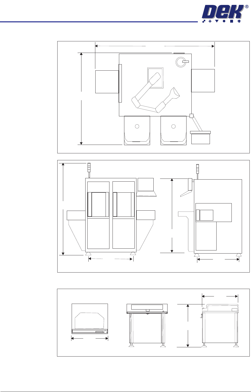
The CHAD WaferMate dimensions are as shown in the graphics below.
The NUTEK Linking Conveyor dimensions are shown below.
Ensure that the first equipment in the line is installed correctly and is level.
The printer(s) are to be levelled such that the transport rails, from one machine
to the next, are all in-line and level. To level the printer carry out the following
procedure.
WaferMate Plan View
1896
1493
WaferMate Front View
WaferMate End View
931
826
2032
1472
Front View
Plan View
End View
1000
802
950 +/- 25
INSTALLATION
EQUIPMENT INSTALLATION
Chapter Issue 1 Aug 11 Wafer Transport Solution 3.17
Power Up 1. Power up the printer.
2. Select Maintenance.
3. Select Diagnostics.
NOTE
The printer’s software automatically checks for the Wafer Transport Solution
hardware via Node 17. If the software fails to recognise the option, users
may set up products but the printer fails to run. To avoid this, the following
section of this procedure is used to check that the software has recognised
that the hardware is fitted.
Hardware
Recognised Check
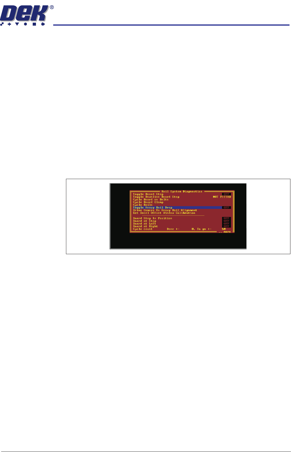
4. Select Rail System.
5. Select Run Diagnost..
6. Check that the following diagnostic elements are included in the list:
• Toggle Heavy Rail Drop
• Set Decel Offset Window Calibration
NOTE
If the above parameters are not listed, the software has not recognised the
hardware is fitted.
7. If the elements are listed, go to Step 11, else:
8. Check that the correct software is loaded for the application.
9. Power down the printer.
10. Referring to drawing 200483 Circuit Diagram -Thin Wafer Handling (located
at the end of this manual); check the connectors and motor of the Heavy
Pallet Servo Node 17.
11. Repeat Steps 1 to 5 above to confirm that the software recognises the
hardware. If the elements are still not listed contact DEK Customer Support
Group for assistance.
12. Exit the diagnostics page. The printer initialises.
Load a Product File 13. From the Ready page select Setup Product.
14. Select Load Product.
15. Select a suitable production product from the list and load the product.