WaferTransportSolutionManual.pdf - 第93页
INSTALLATION EQUIPMENT INSTALLATION Chapter Issue 1 Aug 11 Wafer Transport Solutio n 3.17 Power Up 1. Power up the printer . 2. Select Maintenance . 3. Select Diagnostics . NOTE The printer ’s sof tware automatically che…
INSTALLATION
EQUIPMENT INSTALLATION
3.16 Wafer Transport Solution Chapter Issue 1 Aug 11
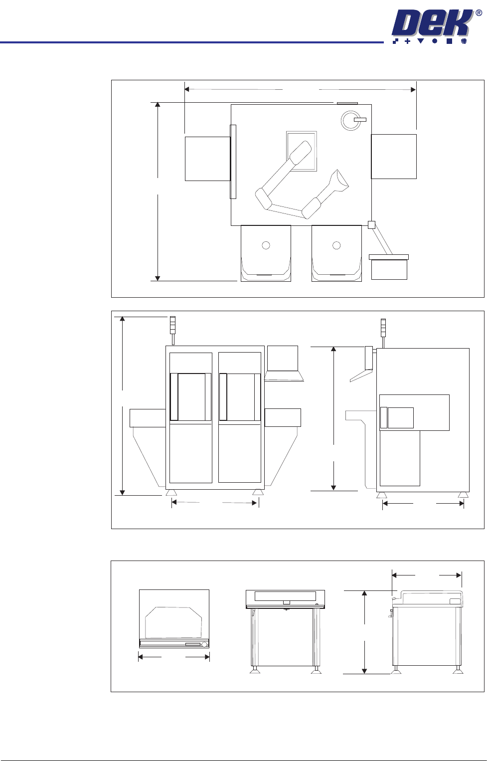
The CHAD WaferMate dimensions are as shown in the graphics below.
The NUTEK Linking Conveyor dimensions are shown below.
Ensure that the first equipment in the line is installed correctly and is level.
The printer(s) are to be levelled such that the transport rails, from one machine
to the next, are all in-line and level. To level the printer carry out the following
procedure.
WaferMate Plan View
1896
1493
WaferMate Front View
WaferMate End View
931
826
2032
1472
Front View
Plan View
End View
1000
802
950 +/- 25
INSTALLATION
EQUIPMENT INSTALLATION
Chapter Issue 1 Aug 11 Wafer Transport Solution 3.17
Power Up 1. Power up the printer.
2. Select Maintenance.
3. Select Diagnostics.
NOTE
The printer’s software automatically checks for the Wafer Transport Solution
hardware via Node 17. If the software fails to recognise the option, users
may set up products but the printer fails to run. To avoid this, the following
section of this procedure is used to check that the software has recognised
that the hardware is fitted.
Hardware
Recognised Check
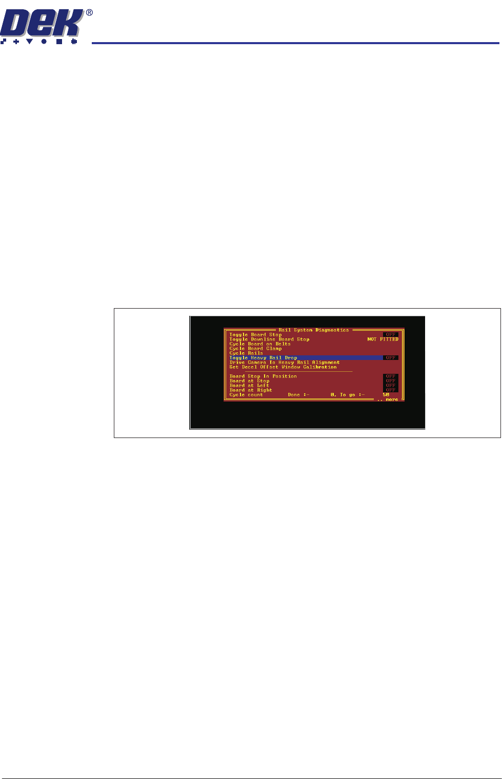
4. Select Rail System.
5. Select Run Diagnost..
6. Check that the following diagnostic elements are included in the list:
• Toggle Heavy Rail Drop
• Set Decel Offset Window Calibration
NOTE
If the above parameters are not listed, the software has not recognised the
hardware is fitted.
7. If the elements are listed, go to Step 11, else:
8. Check that the correct software is loaded for the application.
9. Power down the printer.
10. Referring to drawing 200483 Circuit Diagram -Thin Wafer Handling (located
at the end of this manual); check the connectors and motor of the Heavy
Pallet Servo Node 17.
11. Repeat Steps 1 to 5 above to confirm that the software recognises the
hardware. If the elements are still not listed contact DEK Customer Support
Group for assistance.
12. Exit the diagnostics page. The printer initialises.
Load a Product File 13. From the Ready page select Setup Product.
14. Select Load Product.
15. Select a suitable production product from the list and load the product.
INSTALLATION
EQUIPMENT INSTALLATION
3.18 Wafer Transport Solution Chapter Issue 1 Aug 11
NOTE
If the printer has product files created previously, the user should check that
the product parameters are suitable for this application (physical dimensions
may be unsuitable). The existing product parameters can be edited if
necessary.
Level the Printer 16. Select Tooling.
17. Select Setup Tooling.
18. Select Transport Height.
19. Select Toggle Board Clamps. This step raises the beams up.
20. Level the printer (printer transport heights are to match the downline/upline
systems’ transport height). Full levelling instructions are given in the printer
installation manual.
Level the CHAD/NUTEK Conveyor
WARNING
HEAVY OBJECT. EXTREME CAUTION SHOULD BE EXERCISED WHEN
MANUALLY HANDLING HEAVY ITEMS INTO OR OUT OF THE MACHINE.
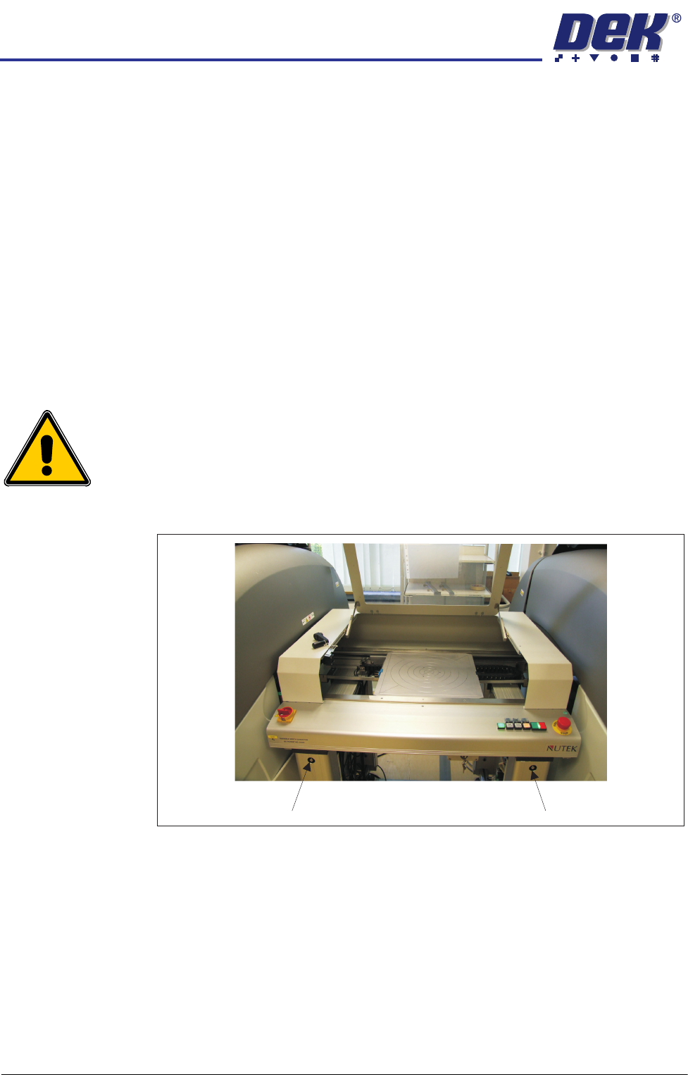
21. Adjust the conveyor rail width to accommodate the pallet.
Figure 3-7 NUTEK Linking Conveyor Rail Width Adjusters
22. The printer is in position and level; align the conveyor system to it (adjust
the four feet a little at a time).
23. If the printer is located to the right of the conveyor, adjust the left side of the
conveyor to bring its transport rails level with the printer transport rails.
24. Level the conveyor to the correct height, matching the printer at transport
height.
25. Manually load a pallet onto the conveyor transport rails.
26. Move the pallet, by hand, into and out of the printer (half and half), check
that it does not bind, lift, or drop when moving on the rail systems of each
machine. Make adjustments to the line levelness and alignment as required.
Rail Width Adjuster Rail Width Adjuster