WaferTransportSolutionManual.pdf - 第95页
INSTALLATION EQUIPMENT INSTALLATION Chapter Issue 1 Aug 11 Wafer Transport Solutio n 3.19 27. Repeat the step s for levelling and apply them to the oth er printer . 28. Remove the pa llet. Pneumatic Connections Three vac…
INSTALLATION
EQUIPMENT INSTALLATION
3.18 Wafer Transport Solution Chapter Issue 1 Aug 11
NOTE
If the printer has product files created previously, the user should check that
the product parameters are suitable for this application (physical dimensions
may be unsuitable). The existing product parameters can be edited if
necessary.
Level the Printer 16. Select Tooling.
17. Select Setup Tooling.
18. Select Transport Height.
19. Select Toggle Board Clamps. This step raises the beams up.
20. Level the printer (printer transport heights are to match the downline/upline
systems’ transport height). Full levelling instructions are given in the printer
installation manual.
Level the CHAD/NUTEK Conveyor
WARNING
HEAVY OBJECT. EXTREME CAUTION SHOULD BE EXERCISED WHEN
MANUALLY HANDLING HEAVY ITEMS INTO OR OUT OF THE MACHINE.
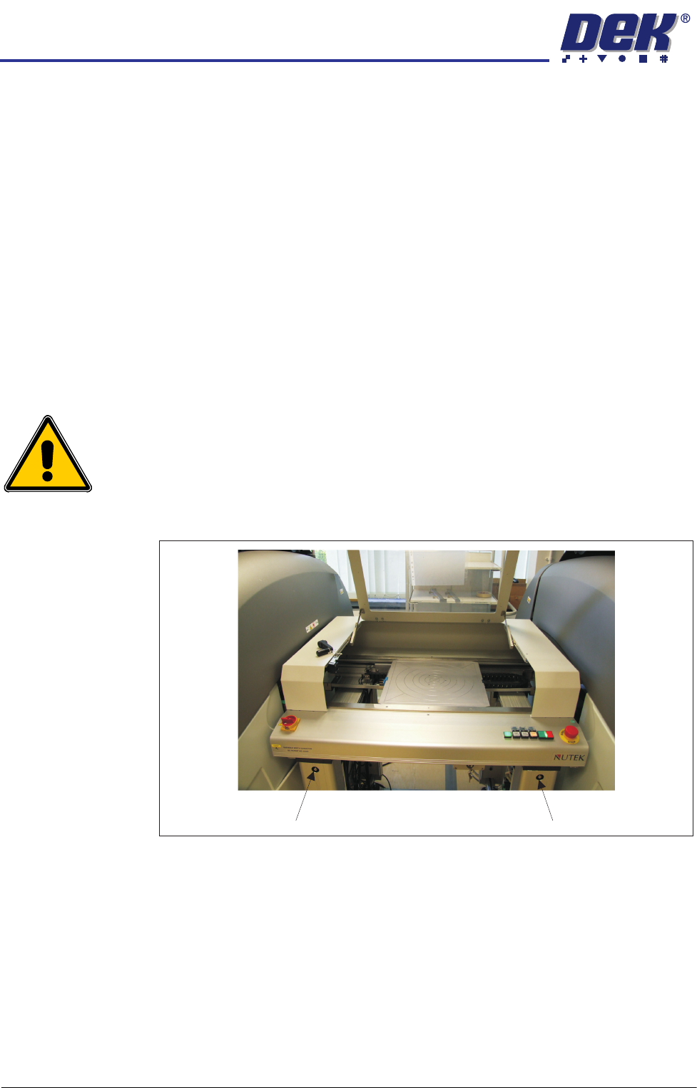
21. Adjust the conveyor rail width to accommodate the pallet.
Figure 3-7 NUTEK Linking Conveyor Rail Width Adjusters
22. The printer is in position and level; align the conveyor system to it (adjust
the four feet a little at a time).
23. If the printer is located to the right of the conveyor, adjust the left side of the
conveyor to bring its transport rails level with the printer transport rails.
24. Level the conveyor to the correct height, matching the printer at transport
height.
25. Manually load a pallet onto the conveyor transport rails.
26. Move the pallet, by hand, into and out of the printer (half and half), check
that it does not bind, lift, or drop when moving on the rail systems of each
machine. Make adjustments to the line levelness and alignment as required.
Rail Width Adjuster Rail Width Adjuster
INSTALLATION
EQUIPMENT INSTALLATION
Chapter Issue 1 Aug 11 Wafer Transport Solution 3.19
27. Repeat the steps for levelling and apply them to the other printer.
28. Remove the pallet.
Pneumatic
Connections
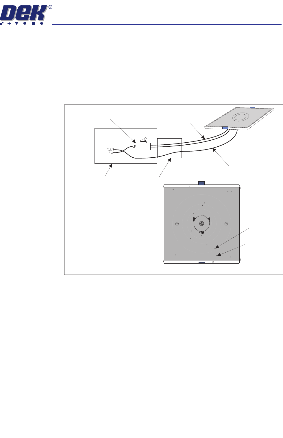
Three vacuum connections from the pallet transfer station are available in its
drag chain. On the pallet, they connect to the two stacked elbow connectors
(pin and wafer) and the single delta ‘tee’ connector (shim). See detail in the
Precision Wafer Pallet Chapter. The connections are push fit, they make the
connections to the underside of the pallet.
Figure 3-8 Simplified View of the Vacuum System
Flow Restrictors The DEK printer flow restrictors need to be balanced to ensure that the pallet
does not ‘drop’ into place in the print area.
1. Open the printhead front cover.
2. Load a pallet into the centre section of the printer.
3. Close the printhead front cover.
4. Press the System button.
5. Select Maintenance.
6. Select Diagnostics.
7. Select Rail System.
8. Select Select Module.
9. Using Decr. or Incr. select Cycle Board Clamp.
10. Select Run Diagnost..
11. From the side of the printer, observe the pallet lift/drop section of the cycle.
The pallet should be placed in a controlled manner onto the support blocks.
If adjustment is not required exit the diagnostic and remove the pallet.
Pallet and
Lift Pin
Elbows
Shim Vacuum
Delta ‘Tee’
Vacuum Switch
Vacuum Control
(See Transfer Station
documentation for details)
Drag Chain
Shim Vacuum
(non-switched)
Pallet & Shim
Pallet & Lift Pin Vacuum
(switched)
Underside of Pallet
INSTALLATION
EQUIPMENT INSTALLATION
3.20 Wafer Transport Solution Chapter Issue 1 Aug 11
NOTE
Safety covers may need to be removed depending upon which side is used
as the view point.
12. If the pallet is placed, with little or no control, the flow restrictors for both rails
need adjustment.
13. Observe the following sequence:
a. The belts drop lowering the pallet onto the support blocks.
b. The snugger moves holding the pallet in position.
c. The snugger force is removed.
d. The pallet, in contact with the belts, lifts clear of the support blocks.
NOTE
Belts move before pallet pick up. The up movement should be smooth and
coincide with the belts start.
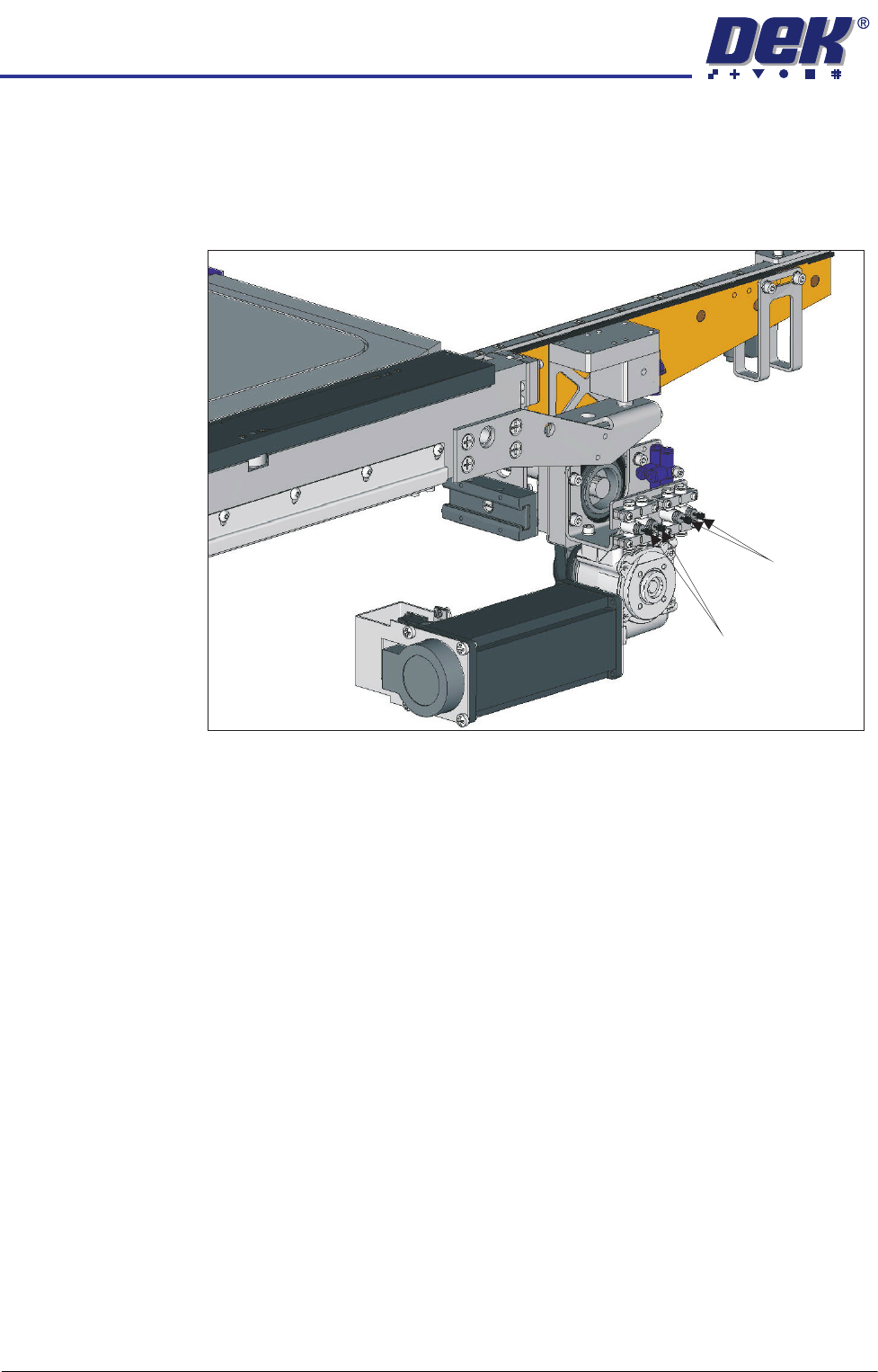
14. Using a flat bladed screwdriver, adjust the Clamps On and Clamps Off
restrictors for both rails. Balance the movement. One side should not be
active before the other nor should the movement at the ends of the rail result
in one end being cantered.
15. Continue cycling and adjusting the rails until a satisfactory movement is
achieved.
16. Exit Diagnostics.
17. Refit the safety covers.
Clamps OFF
Clamps ON