WaferTransportSolutionManual.pdf - 第97页
INSTALLATION EQUIPMENT INSTALLATION Chapter Issue 1 Aug 11 Wafer Transport Solutio n 3.21 Customer Product Configuration WARNING HEAVY OBJECT. EXTREME CAUTION SHOULD BE EXERCIS ED WHEN MANUALLY HANDLING HEAVY ITEMS INTO …
INSTALLATION
EQUIPMENT INSTALLATION
3.20 Wafer Transport Solution Chapter Issue 1 Aug 11
NOTE
Safety covers may need to be removed depending upon which side is used
as the view point.
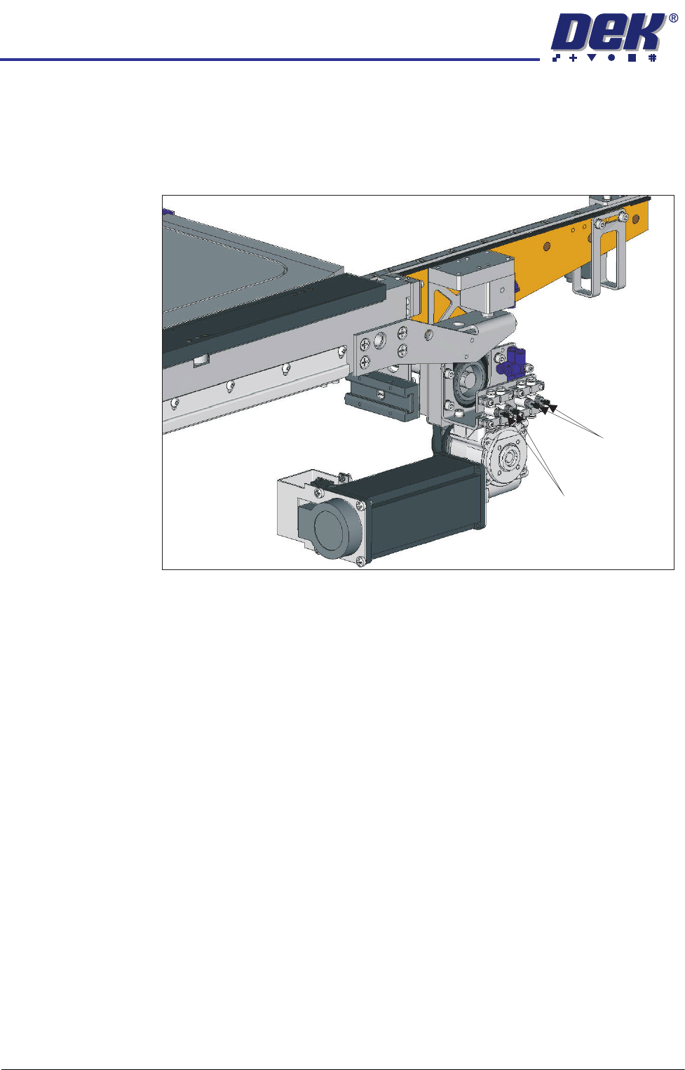
12. If the pallet is placed, with little or no control, the flow restrictors for both rails
need adjustment.
13. Observe the following sequence:
a. The belts drop lowering the pallet onto the support blocks.
b. The snugger moves holding the pallet in position.
c. The snugger force is removed.
d. The pallet, in contact with the belts, lifts clear of the support blocks.
NOTE
Belts move before pallet pick up. The up movement should be smooth and
coincide with the belts start.
14. Using a flat bladed screwdriver, adjust the Clamps On and Clamps Off
restrictors for both rails. Balance the movement. One side should not be
active before the other nor should the movement at the ends of the rail result
in one end being cantered.
15. Continue cycling and adjusting the rails until a satisfactory movement is
achieved.
16. Exit Diagnostics.
17. Refit the safety covers.
Clamps OFF
Clamps ON
INSTALLATION
EQUIPMENT INSTALLATION
Chapter Issue 1 Aug 11 Wafer Transport Solution 3.21
Customer Product Configuration
WARNING
HEAVY OBJECT. EXTREME CAUTION SHOULD BE EXERCISED WHEN
MANUALLY HANDLING HEAVY ITEMS INTO OR OUT OF THE MACHINE.
The following procedures align the top of the product to the top surface of the
top plates. A reference check is made using the setting bar (201121). The
shim and pallet assembly used for these checks should be those used for a
customer production product.
Reference Check NOTE
The precision pallet, shim, rail top plates and setting bar are all manufactured
to a high degree of flatness and are susceptible to surface flaws that can
degrade their function. In the following procedure hard tooling is used in
contact with these surfaces which may cause markings or more significant
damage, if not handled carefully. Tooling used must be clean and blemish
free. All effort must be made to avoid dragging, dropping or knocking tools on
the exposed surfaces.
For many instances, this check gives the level of accuracy required to produce
good quality prints; for the highest accuracy, carry out this check and the
accuracy check, refer to the section - Accuracy Check for details.
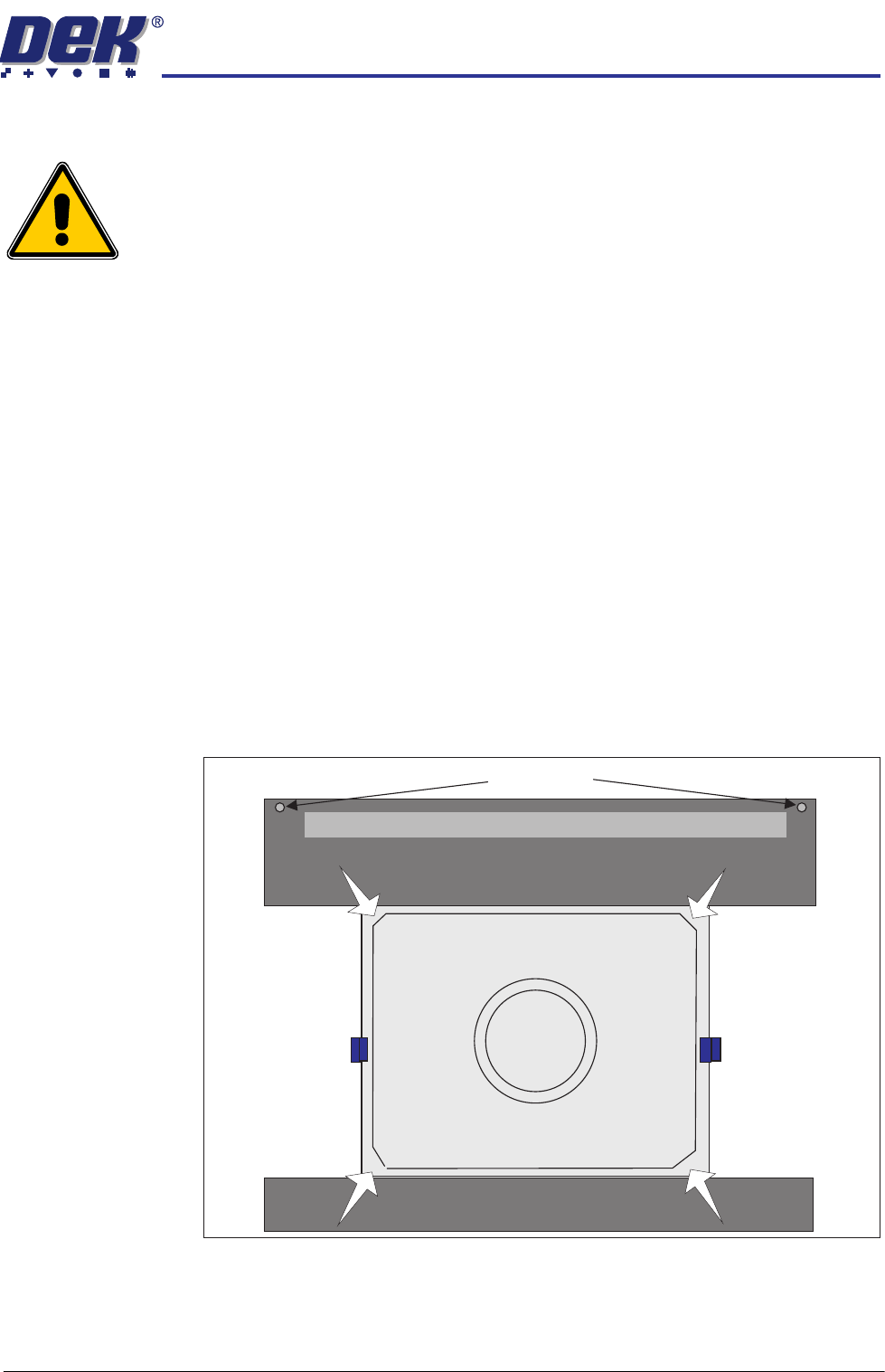
1. Press the pallet down in each of the four corners and check for any rocking
movement; if rocking is noted, complete the following steps; for no rocking,
continue with the accuracy check.
2. Close the front printhead cover.
Pallet Shimand
Front Transport Rail
Rear Transport Rail
Safety Screws
Sphere Dump Tray Removed

INSTALLATION
EQUIPMENT INSTALLATION
3.22 Wafer Transport Solution Chapter Issue 1 Aug 11
NOTE
Two safety screws are used to support the rear of the rear top plate. They
screw onto a pair of lift cylinder arms underneath the top plate, this provides
the support. The screws should be wound out (away from each lift cylinder
arm) until there is no contact. When the top plate adjustment is complete,
they should be wound down to contact (contact not distort) the lift cylinder
arms.
3. Remove the sphere dump tray from the rear transport rail; retain for later
refit.
NOTE
The following procedure is used to determine which adjusters need to be
adjusted to remove any rock in the pallet.
4. Press the System button.
5. Select Exit.
6. Using Decr. or Incr. navigate to Rising Table.
7. Select Select Module.
8. Using Decr. or Incr. navigate to Raise Table to Vision Height
9. Select Run Diagnost..
10. Open the printhead front cover. The software pauses and displays the
System Error - System Suspended While Covers Open warning.
11. Fit the two setting rods.