WaferTransportSolutionManual.pdf - 第99页
INSTALLATION EQUIPMENT INSTALLATION Chapter Issue 1 Aug 11 Wafer Transport Solutio n 3.23 Figure 3-9 Setting Rods Fitte d Through Both Rails 12. Activate the E S top . 13. Remove the Pallet and Shim. 14. Align setting ba…

INSTALLATION
EQUIPMENT INSTALLATION
3.22 Wafer Transport Solution Chapter Issue 1 Aug 11
NOTE
Two safety screws are used to support the rear of the rear top plate. They
screw onto a pair of lift cylinder arms underneath the top plate, this provides
the support. The screws should be wound out (away from each lift cylinder
arm) until there is no contact. When the top plate adjustment is complete,
they should be wound down to contact (contact not distort) the lift cylinder
arms.
3. Remove the sphere dump tray from the rear transport rail; retain for later
refit.
NOTE
The following procedure is used to determine which adjusters need to be
adjusted to remove any rock in the pallet.
4. Press the System button.
5. Select Exit.
6. Using Decr. or Incr. navigate to Rising Table.
7. Select Select Module.
8. Using Decr. or Incr. navigate to Raise Table to Vision Height
9. Select Run Diagnost..
10. Open the printhead front cover. The software pauses and displays the
System Error - System Suspended While Covers Open warning.
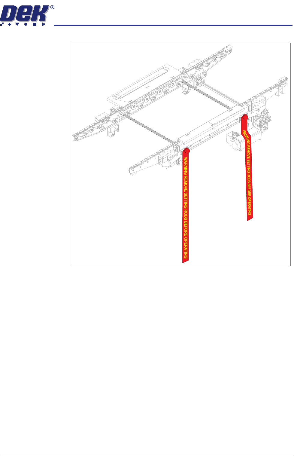
11. Fit the two setting rods.
INSTALLATION
EQUIPMENT INSTALLATION
Chapter Issue 1 Aug 11 Wafer Transport Solution 3.23
Figure 3-9 Setting Rods Fitted Through Both Rails
12. Activate the E Stop.
13. Remove the Pallet and Shim.
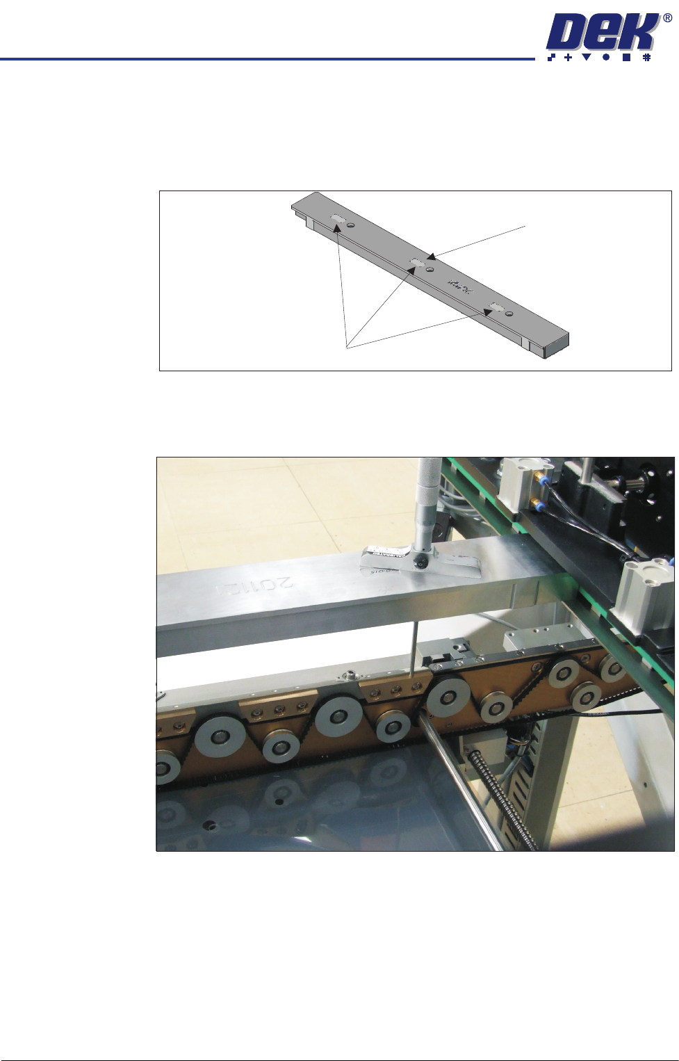
14. Align setting bar (201121) in the chase, with the holes over the front rail.
15. Insert the depth micrometer into the left/right holes of the setting bar;
touching the support blocks.
16. Note the reading of the depth micrometer to the support blocks.
INSTALLATION
EQUIPMENT INSTALLATION
3.24 Wafer Transport Solution Chapter Issue 1 Aug 11
NOTE
All setting bars are marked with unique readings expressing the bar’s
flatness. The centre reading is always zero, the other readings are relative
to the centre. These markings are known as the setting bar flatness
calibration figures.
17. Remove the depth micrometer.
18. Insert the depth micrometer into the left hole of the setting bar. The depth
micrometer tip contacts the left hand pallet support block.
Setting Bar Flatness Calibration Figures
Centre is Zero (0.00)